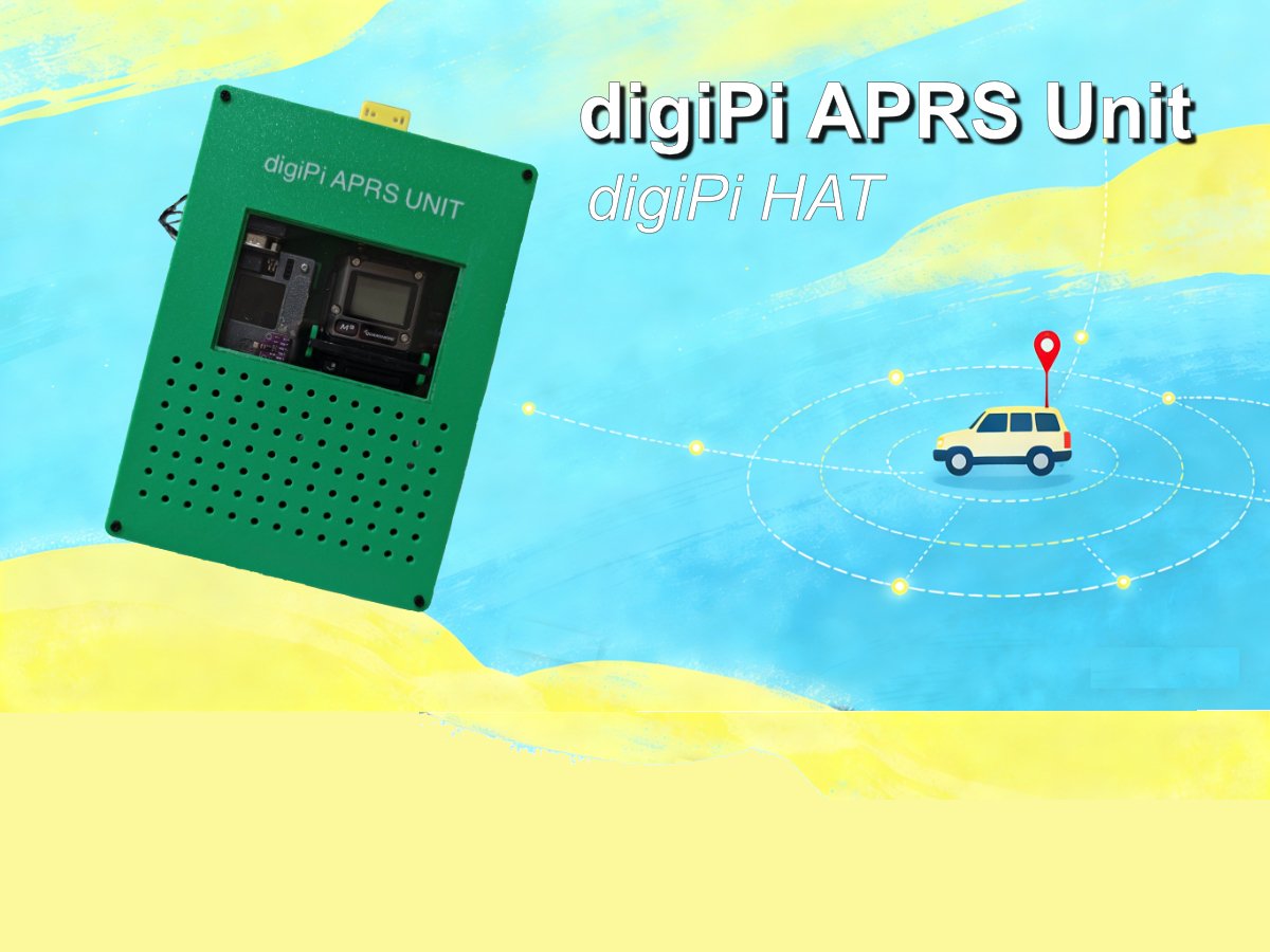
digiPi is a software system that is based on Linux for amateur radio digital communications. Its primary function is to make various amateur radio digital modes easily accessible via Wi-Fi through a standard web browser. It simplifies amateur radio digital modes operation by providing a pre-configured, bootable image for a Raspberry Pi. It supports a wide range of amateur radio digital modes, from some vintage modes like rtty, and psk31 to some more modern ones like aprs, ft8 and js8call.
digiPi HAT is an add-on board for raspberry Pi for working digital modes on some radios or handheld radios with no USB or TNCs. The board integrates key components such as a sound card to make it become a sound card modem, circuitry for Push-to-Talk (PTT) control, USB-TTL CAT control, and also includes an on-board TFT LCD display(for APRS), buttons, and connectors for optional GPS or environmental sensors. The board works seamlessly with the digiPi software system. It interfaces radios through a DB9-F connector, which handles both of the audio and the PTT control.
I have set up my digiPi system for a while. It normally works as an APRS iGate or a digi-peater (sometimes)for serving our local aprs community. I have a UV-K6 connected to it by the DB9-F connector. The system works smoothly and has decoded lots of aprs messages. I put my digiPi system right on the corner of my workbench. I have to say, it works fantastically as a whole, but since the system consists of a raspberry Pi, a digiPi HAT, and a radio with cables connected to digiPi HAT, it always make my desktop look messy. So I would like the system to be a single unit, and I could put it anywhere, perhaps for portable or my car, or a fixed place on my balcony where my VHF antenna is located. The system should work as a whole in a single unit. It’s the key point.
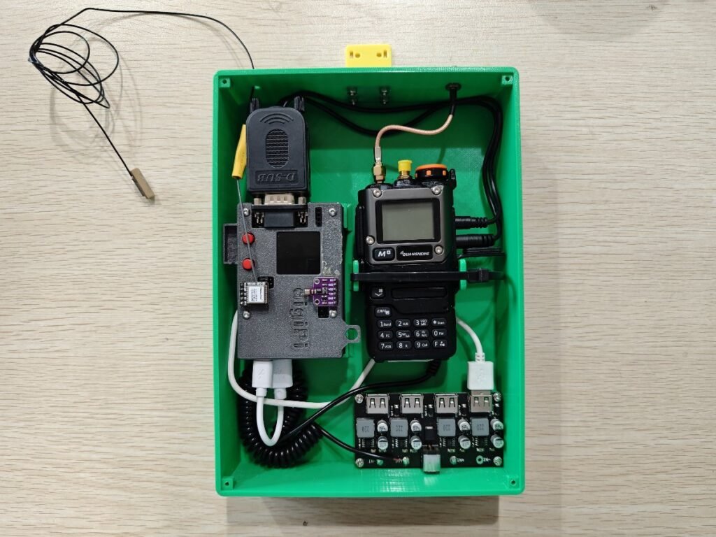
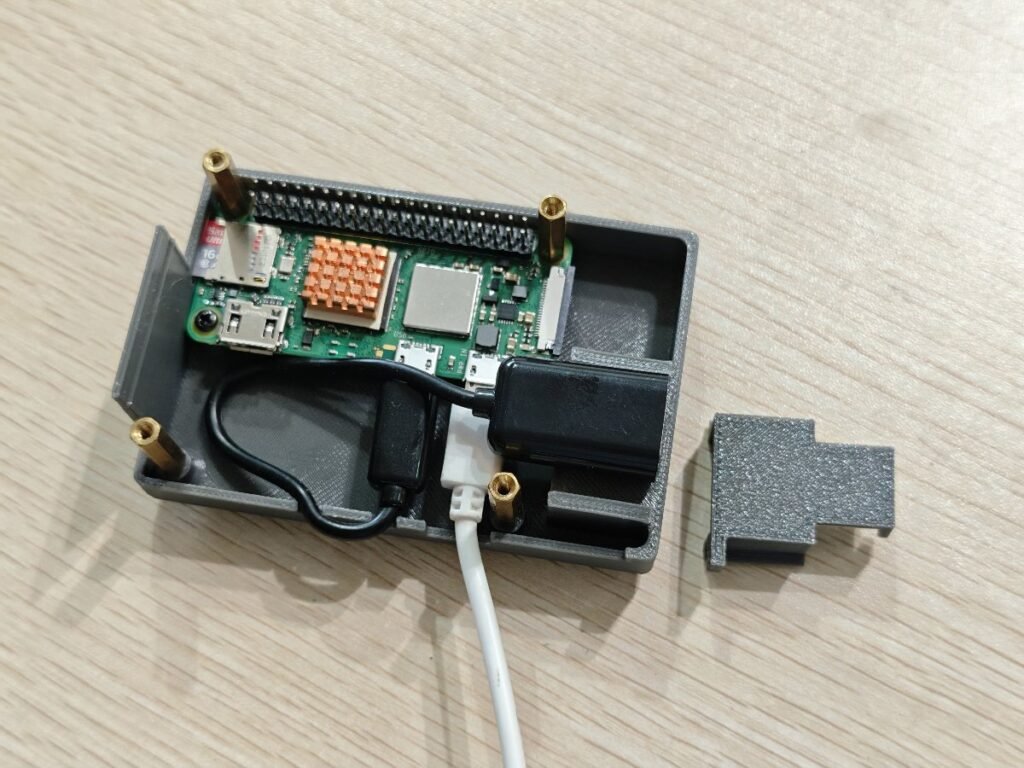
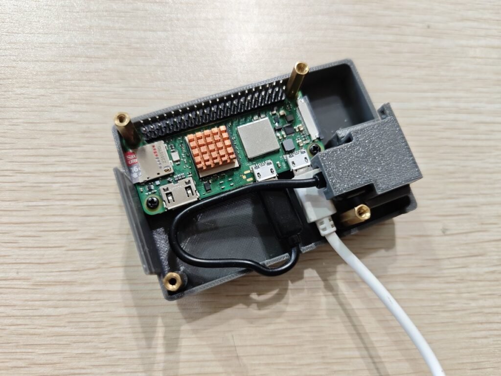
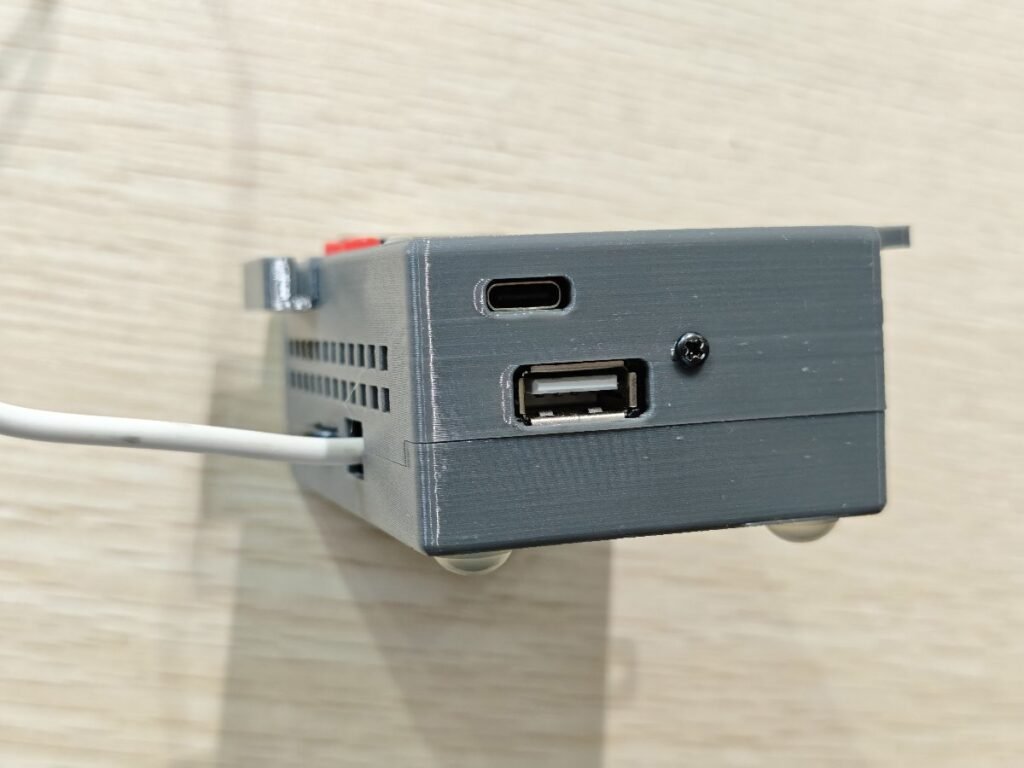
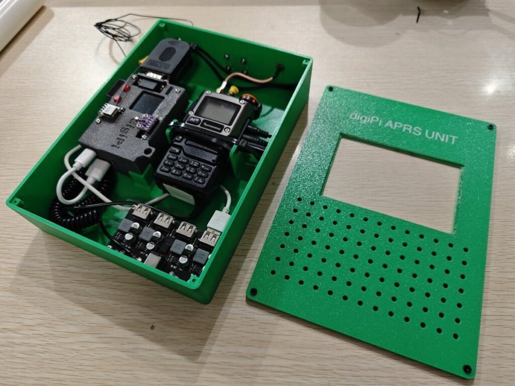
Here is my design. I 3d-printed a big enclosure that could hold the whole digiPi stuffs. The enclosure is 236mm x 170mm x 52mm with a SMA port and holes for GPS module and power supply. There is a short piece of coax jumper to my UV-K6 radio inside the box. The radio is powered through a dummy battery installed on the back of the radio. The dummy battery is powered by a 12V from the DC-USB buck converter board which is installed at the bottom right corner of the enclosure. The raspberry Pi and digiPi HAT get the power from the buck converter’s USB port. See the picture below. The radio gets power from its dummy battery.
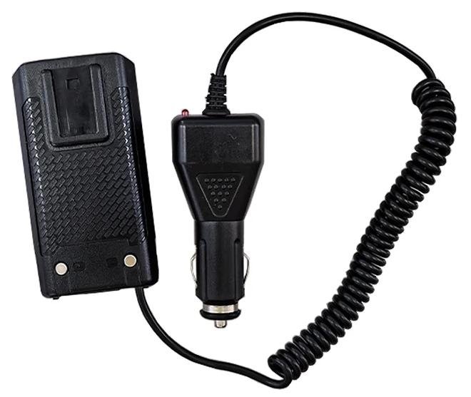
This is the dummy battery with the car cigarette lighter plug. I directly cut the cigarette lighter plug off, and soldered the cable directly onto the input of DC-USB board. Pay attention to the polarity when doing this.

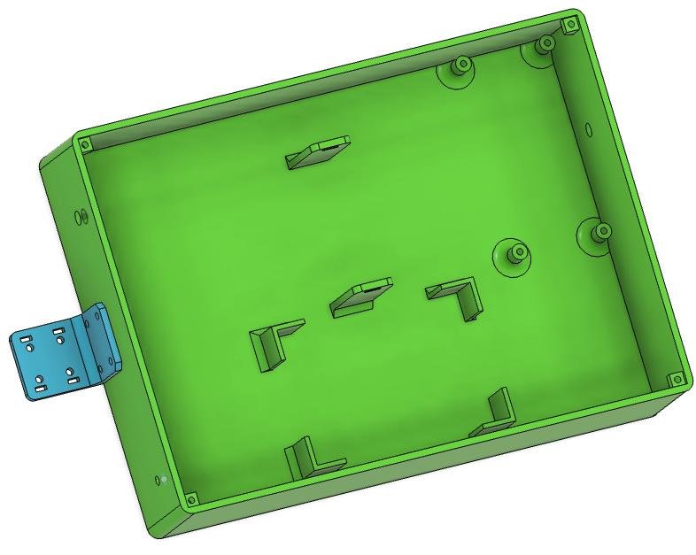
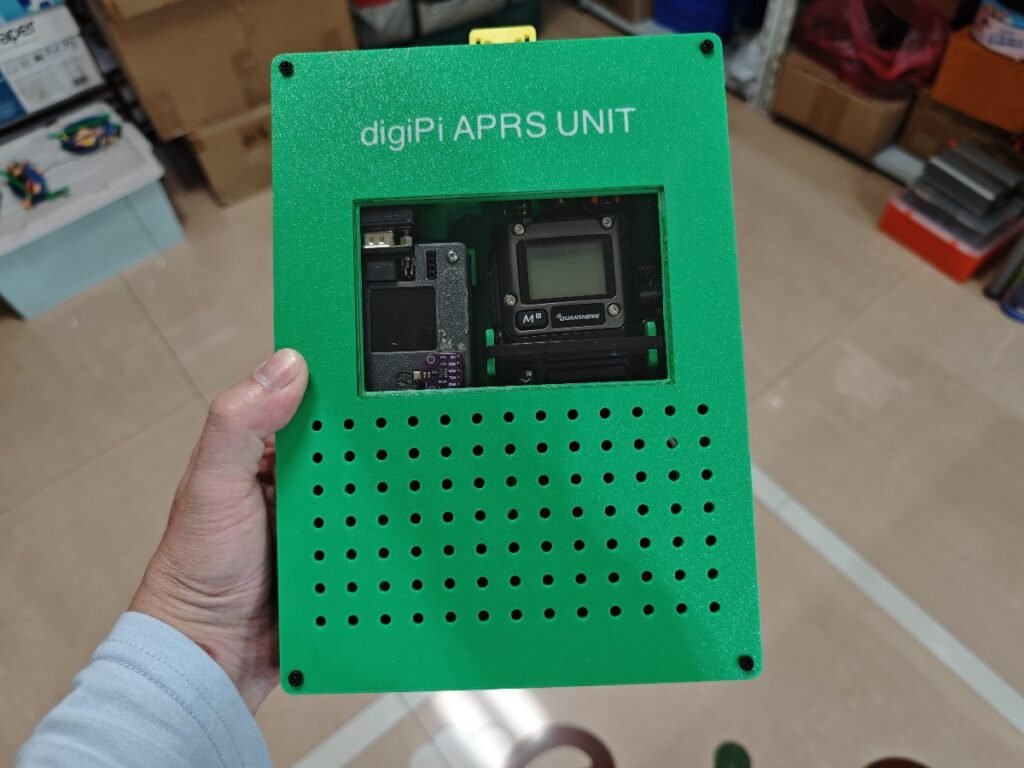
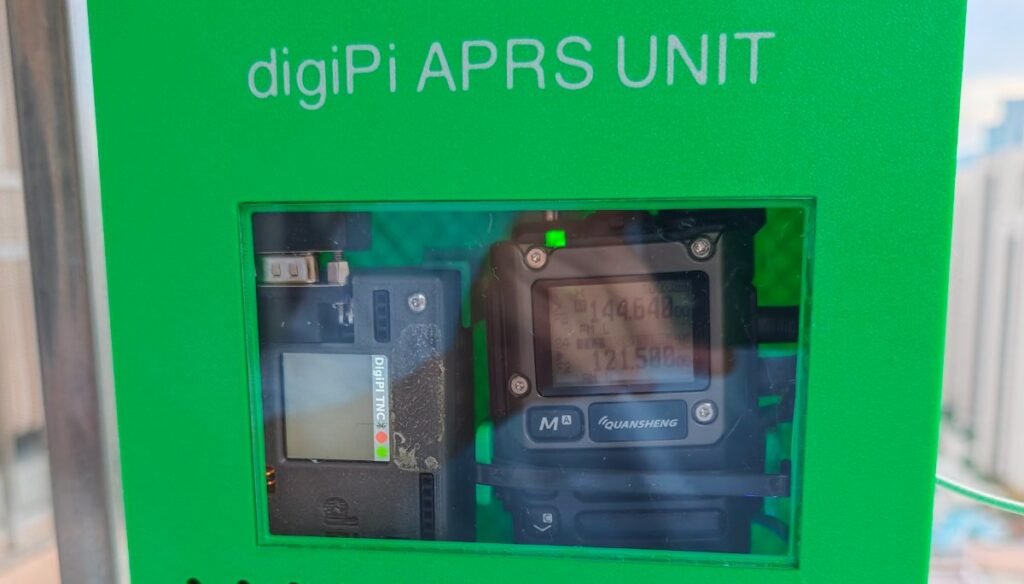
The 4 right-corner walls keep the digiPi in position, and the two pillar standoffs and a cable tie will hold the radio there. On the top cover, a piece of clear acrylic sheet is used so that we could see the screen displays from both the digiPi and the radio.
The gps cable goes through the hole on the left, and the antenna cable is mounted on the right position. The DC-USB board is put on the bottom right corner. The digiPi case in the picture is for raspberry Pi zero 2W, not the regular Pi4 or Pi5 ones.
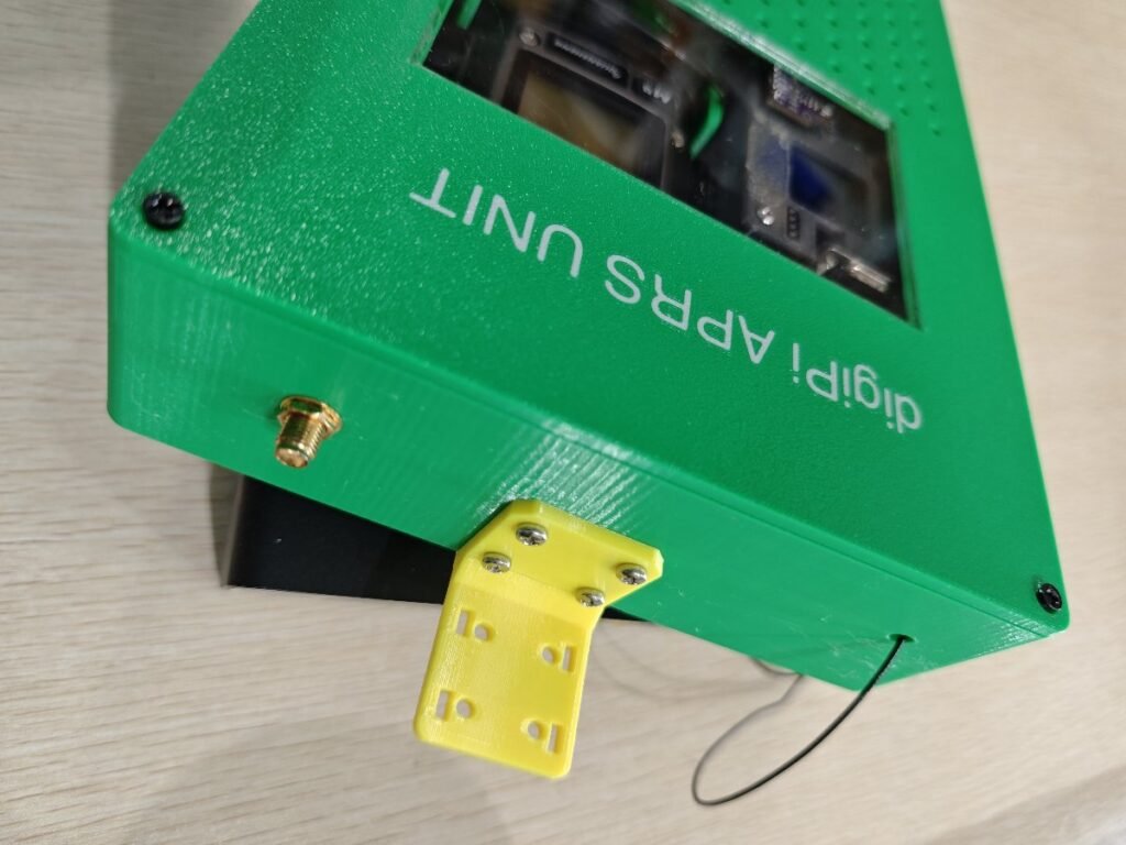
A 3mm acrylic sheet is used on the top cover, in order to view the screen contents.
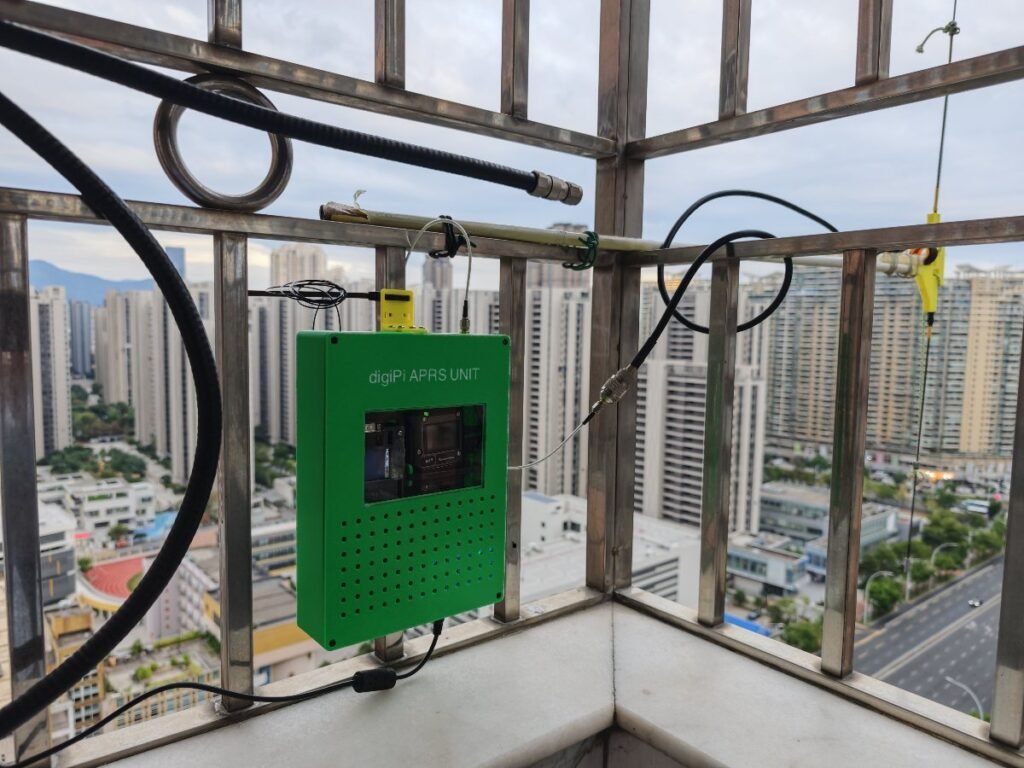
The digiPi APRS UNIT was mounted on the balcony rail.
Project Files:
https://drive.google.com/file/d/1m4JTirzWP_5-hwPjMa4IRxJ3gzuNmwjw/view?usp=sharing