Background:
For amateur radio operators engaging in Portable Operations in the Parks (POTA) and Summits on the Air (SOTA), reliable, efficient power is the backbone of successful activations. These activities often take place in remote, off-grid locations where solar power becomes a vital energy source. An MPPT (Maximum Power Point Tracking) controller is not just a convenience but a critical component for maximizing solar energy harvest and ensuring seamless radio operations in these challenging environments. However, most commercial MPPT controllers come with a high cost (e.g., $200+). Thus, building a 1kW MPPT controller based on an open-source project emerges as a cost-effective solution.
I stumbled upon Angelo Casimiro’s open-source project ”DIY 1kW MPPT Solar Charge Controller”. Its ESP32-based WiFi + Bluetooth feature, low cost (around $25), and high scalability (supporting 80V input/50V output) perfectly suit portable scenarios, prompting me to replicate and modify it perhaps. I then happily found that there was already a remixed version of it, which includes all of the buttons onto the MPPT board. So I made the board quickly and finally collected all of the parts needed for this project.
Disclaimer: Clearly state that the project is based on Angelo Casimiro’s open-source design. This article only shares personal construction processes and functional extensions, with no claim to original design.
The Key Concept of a MPPT Controller:
Here I would like to re-state the basic working principle of a MPPT controller based on my understanding:
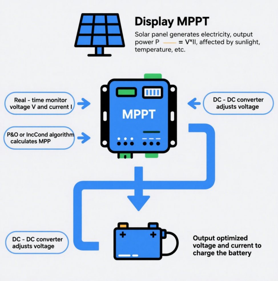
An MPPT (Maximum Power Point Tracking) controller is a critical component in solar energy systems, designed to maximize energy harvest from solar panels by ensuring they operate at their Maximum Power Point (MPP)—the optimal voltage-current combination for peak power output under varying conditions (sunlight, temperature, shading). Here’s a simplified breakdown:
1. The Need for MPPT: Solar Panels’ Non-Linear Output
Solar panels produce DC electricity, but their power output (P = V × I) isn’t constant. Factors like cloud cover, temperature, or panel angle shift their IV curve (voltage vs. current), creating a single MPP where power peaks. Without MPPT, panels often operate inefficiently, waste up to 30% of potential energy compared to basic PWM controllers.
2. Core Working Principle
- Real-Time Monitoring: Continuously measures panel voltage (V) and current (I) to calculate power (P = V × I).
- MPP Tracking Algorithm: Uses algorithms to “hunt” for the MPP:
- Perturb & Observe (P&O):
- Slightly perturbs voltage (e.g., increases/decreases it) and observes power changes.
- If power rises, continue perturbing in the same direction; if it falls, reverse direction.
- Analogy: Like turning a dial to find the “sweet spot” in a radio signal—adjusting until the strongest signal (power) is found.
- Incremental Conductance (IncCond):
- Compares instantaneous conductance (I/V) with incremental conductance (ΔI/ΔV). At MPP, ΔI/ΔV = -I/V (slope of power curve = 0).
- Adjusts voltage to match this condition, ideal for fast-changing light.
- Perturb & Observe (P&O):
- Voltage Matching via DC-DC Converter:
- Uses a buck/boost converter to adjust panel voltage to match battery voltage while preserving maximum current.
- Example: If a panel outputs 20V/5A (100W) and the battery needs 12V, the converter steps down voltage to 12V and increases current to ~8.3A (nearly 100W, minus minor losses).
3. Adaptation to Changing Conditions
MPPT controllers dynamically adjust to environmental shifts:
- Strong Sunlight: Prioritizes higher voltage (e.g., 18V) to hit MPP for max power.
- Weak Sunlight/Shading: Shifts to lower voltage (e.g., 12V) to maintain current, ensuring energy capture even in suboptimal conditions.
- Temperature Changes: Cold panels raise voltage; hot panels lower it—MPPT compensates to stay at MPP.
4. Why It Works Better Than PWM
Unlike simple PWM controllers (which fix voltage/current), MPPT:
- Optimizes for Efficiency: Up to 30% more energy harvest by exploiting the full IV curve.
- Flexible Voltage Conversion: Handles panels with higher voltages than batteries (e.g., 48V panels charging 12V batteries).
- Battery Protection: Delivers stable, optimized charging currents, prolong battery life.
5. Conclusion:
An MPPT controller is a “smart optimizer” that ensures solar panels always work at their peak, adapting to real-time conditions to squeeze every watt from sunlight—essential for off-grid systems, portable setups (like ham radio), and grid-connected installations alike.
Hardware Building Notes:
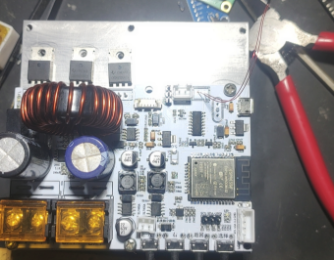
Some of the parts may be slightly different from those ones used in the original project. For example, the main inductor used here is rated only 10A, and the fuels are rated only 5A. Because all I need is a MPPT controller that could charge up my LiFePO4(14.4V/20Ah) for Ham Radio field or portable operation. A 5A charging rate is sufficient for me, and the solar panels I have are only 60W with 18V output.
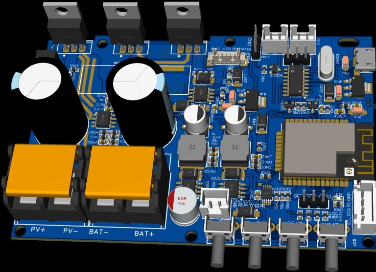
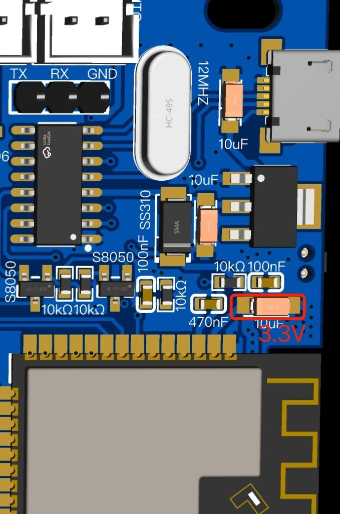
As the values of the components are printed directly on the PCB, I don’t have to check the schematic while picking and placing the parts on the PCB, but there still has some key points of which you have to take care when assembling the PCB.
- Don’t install R34, which is valued as ‘RC’ in the schematic.
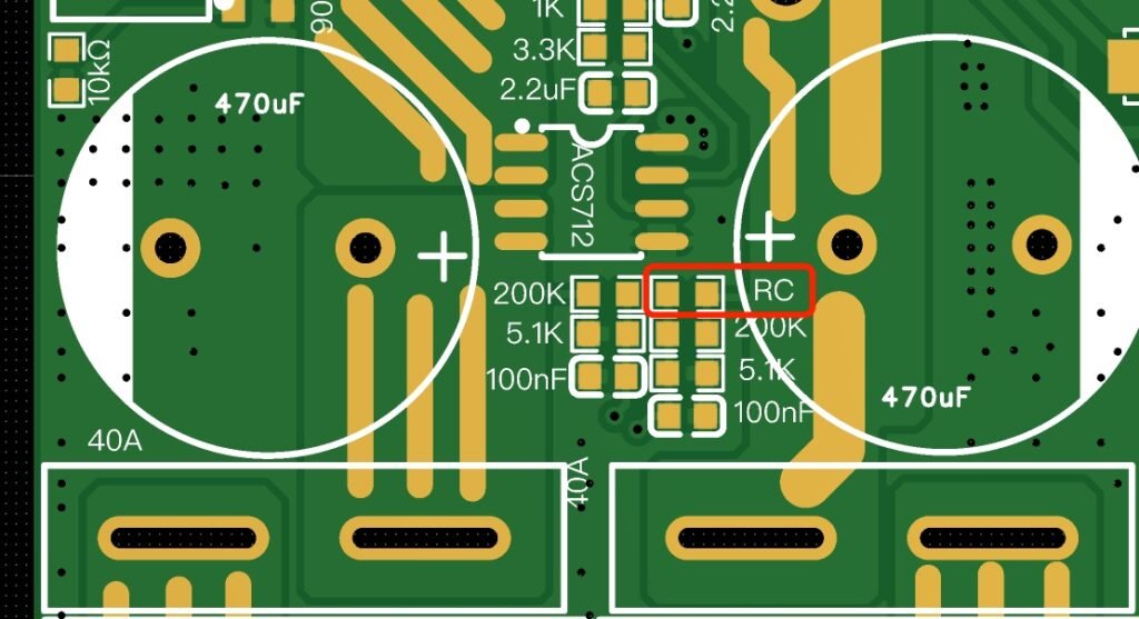
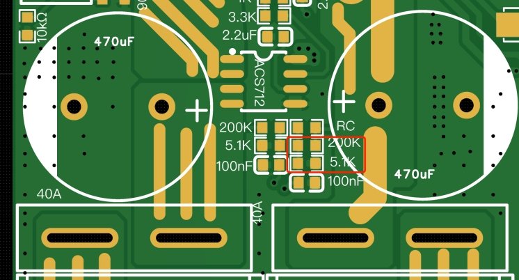
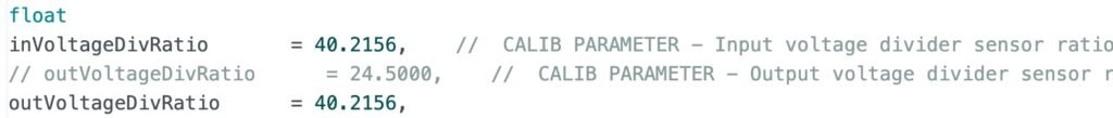
- As the R32 and R33 are labeled 200k and 5.1k, they are the resistors in series for a divided voltage as the ADC input, you have to change ratio settings for output voltage in the Arduino code. I changed both of the input and output voltage ratio to the same value, 40.2156.
- R17, R18 and R19 are labeled as 15k, 15k, and 1k. It’s a mistake here, it only gives 10.6V out, which is not able to trig U12(BS1212). In order to rise up the output voltage to 12V, we have to change the values a little, for me, they are 18k, 18k and 1k, which gives 12.5V out, and it’s fine for U12.
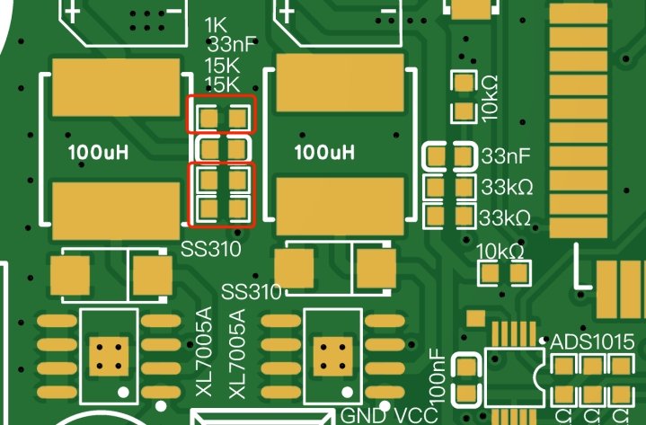
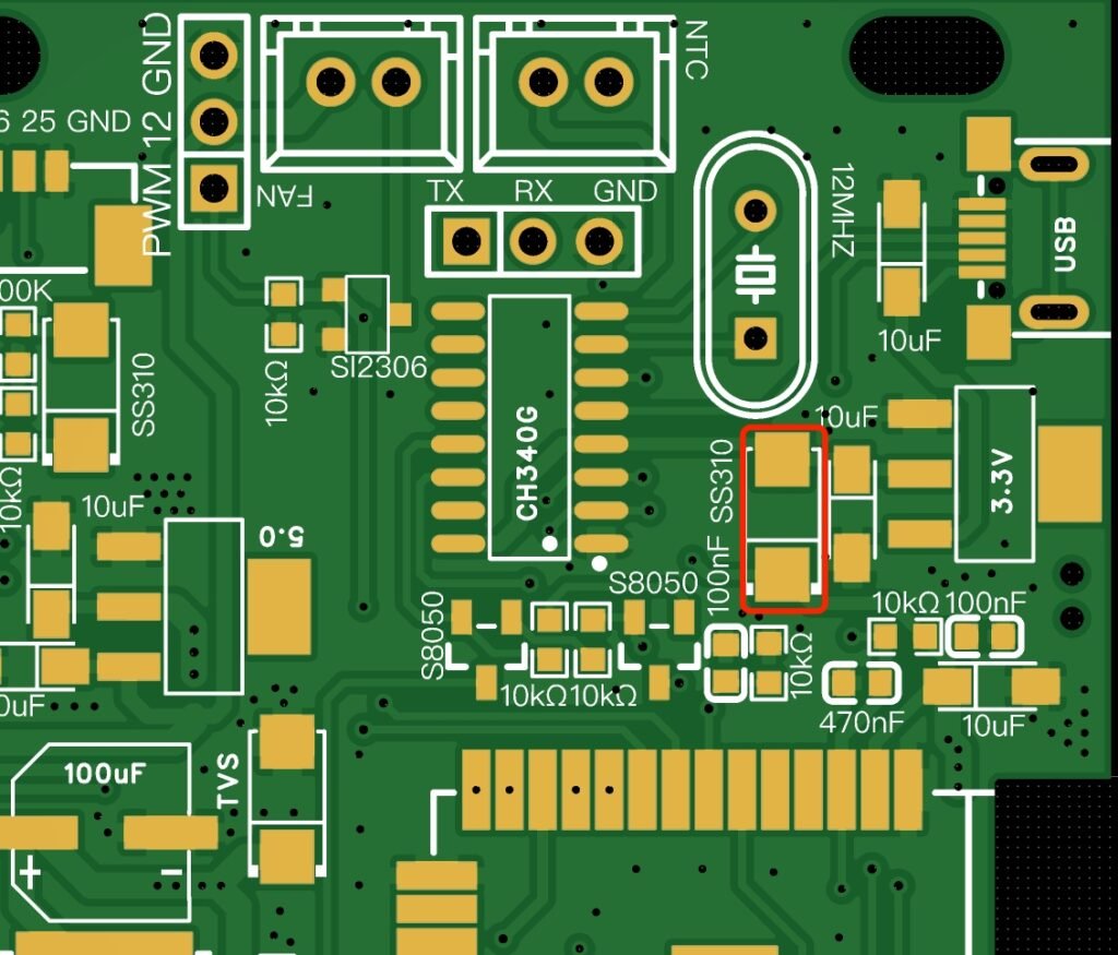
- I didn’t install D1(SS310), as I didn’t like the unit to be powered by USB when it’s plugged into a computer. The firmware downloading sometimes failed and got no response while the controller was powered both by solar panel and USB at the same time. Because sometimes it didn’t make the ESP32 reset and ready for downloading the code.
When all of the SMD parts were placed correctly, I heated my board by my homemade PCB heater. If you don’t have the similar reflow heater, just use a hot air gun to heat the parts up.
Now, it’s time to solder the through hole parts. Solder all of the parts except U4, U5 and CN5 as we have to test these ports before installing them, this is to avoid the “flying smoke” when it’s initially powered up. When things are done, proceed a double check for the component values you used on the board.
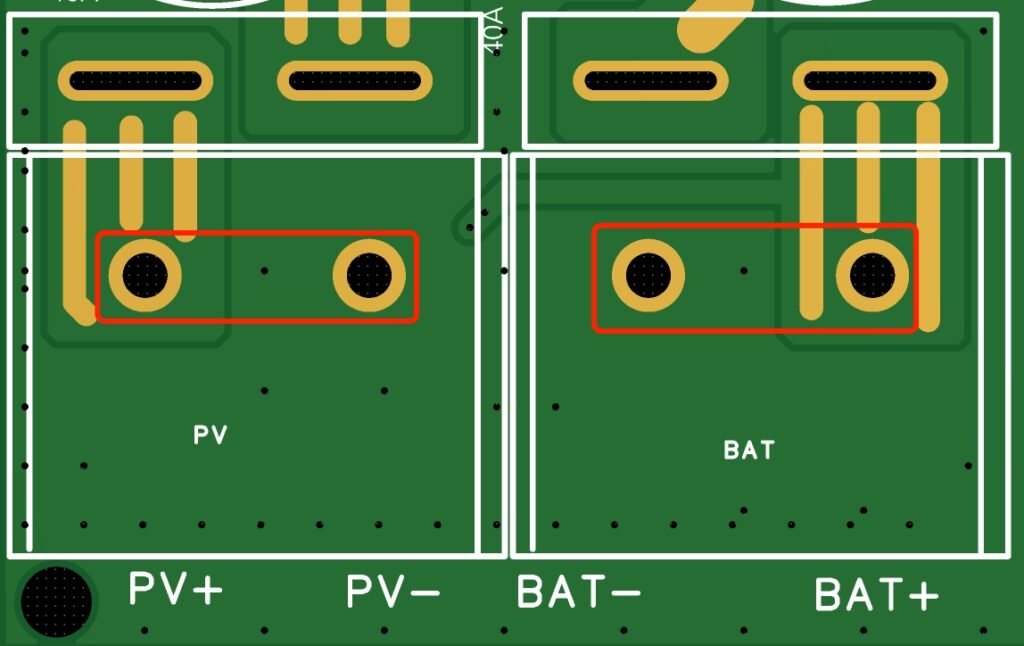
Next, use a DVM to measure the resistance, on both the input and output ports, make sure it doesn’t show a near zero ohm, or hear beeps from the DVM’s buzzer.
If everything goes smoothly, solder U4, U5 and CN5. By the way, in order to ensure a smooth firmware downloading, please double check the soldering quality of the micro-usb connector.
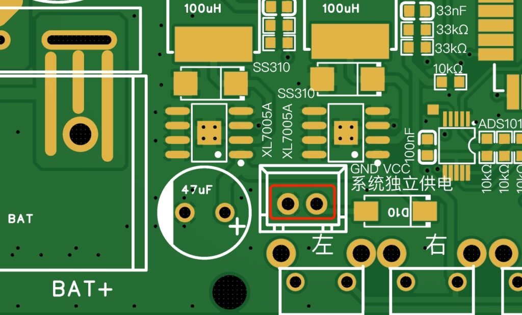
Next, turn on your lab power supply, adjust the output DC voltage to 18V, and be sure to limit the output current to 100mA or less, this is to protect board from burning if there has something wrong. Apply the 18V DC to CN5 to see if there has some currents drawing, and it should be around 50 or 60mA. Use a DVM to measure the voltage across D2, C12 and C13, and they should be 3.3V, 12.5V and 5V. If not, you have to check those components around U7 (XL7005A) and U8(XL7005A), make sure they are not in wrong conditions. Also check the voltage across C25, it should be 3.3V, otherwise, the ESP32 will not work.
Firmware Notes:
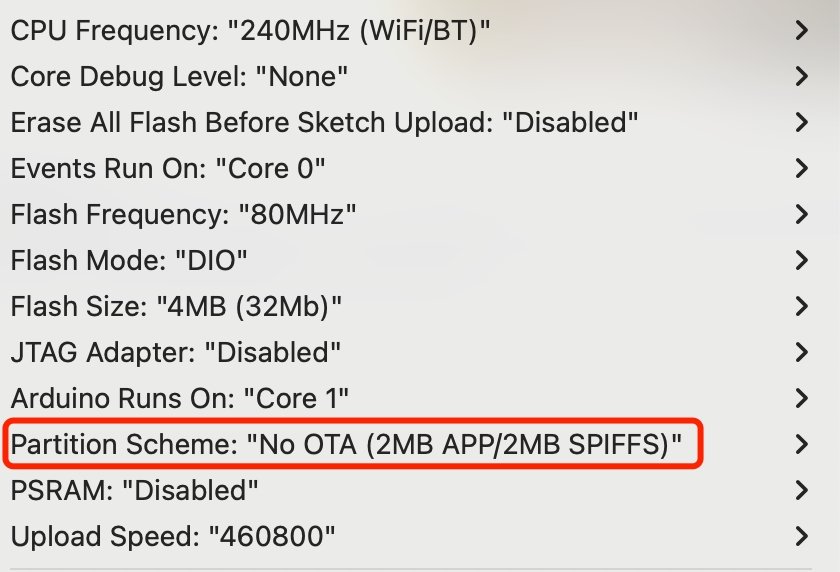
Before opening the Arduino IDE, don’t forget to copy all of the project libraries to your Arduino IDE’s library folder, otherwise, the compiling of the code will not be successful. Once it’s done, open your Arduino IDE and load the sketch. From the “Tools” menu, change the board to “ESP32 Dev Module”, and select the correct serial port. Set the board parameters as the following. Also pay attention to the partition scheme, you will fail in compiling the code if it’s configured incorrectly. Next, press the compile button to see if it could be compiled successfully.
Before loading the firmware to ESP32, we have to change somethings in the code.
1. WiFi Credentials:
You have to input your wifi ssid and password manually here. As I changed the code to use the MultiWifi library, there are 3 pairs of wifi ssid and passwords. If you don’t have so many wifi credentials, just use one pair, and keep others unchanged.
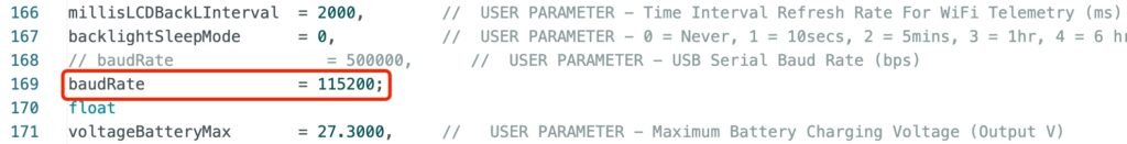
2. Serial Baud-rate:
The original code uses 500000 as the baudrate for serial communication, but I have changed it to 115200 which is more commonly used.
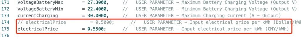
3. Electrical Price:
As the code has the feature for calculating the amount of money that the solar power has harvested, you can change the electrialPrice in the code.
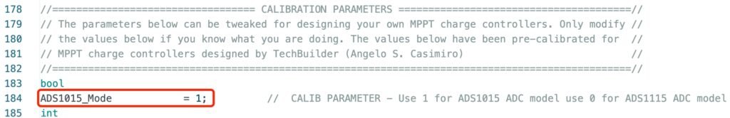
4. ADC Chip Selection:
The project supports two ADC chips, ADS1015 (12bit) and ADS1115 (16bit). If you use ADS1115, you have to change the vaule here to 0.
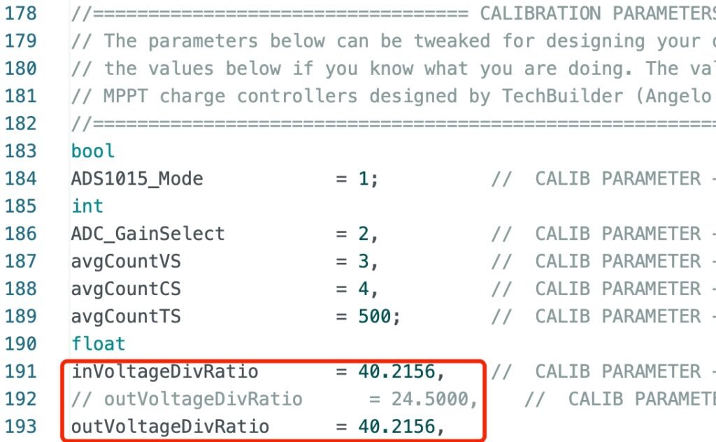
5. Change the Voltage Divider Ratio:
I used the same resistors in series for both the input and output voltagte sampling, so I changed the values to the following.
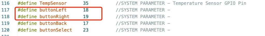
6. Swap the GPIO Number for Left and Right Button:
The GPIO numbers used in my project for buttons are slightly different from the original one, please change the GPIO numbers for buttonLeft and buttonRight to the following:
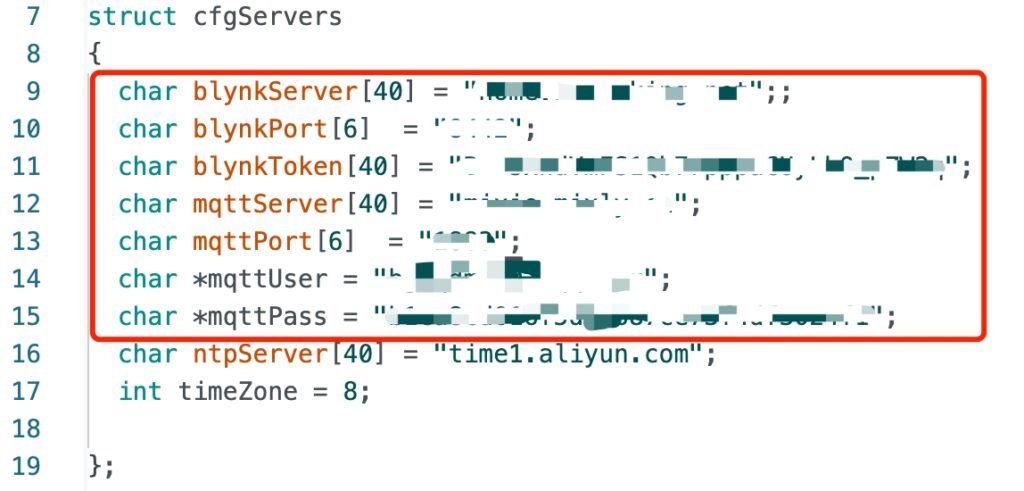
7. Change the IOT server information:
The project uses Blynk (V1.0) as the IOT implementation. Though it’s deprecated, it’s still usable and free. The functionality of Blynk (V1.0) is way enough for the project in this kind. The downside is that the Blynk public server is not available now, but you could set your own server up by using a raspberry Pi 2, Pi3 or Pi4. Other single board computers like Orange Pi or Banana Pi are able to do the same things.
As for the OS, I would definitely recommend to use the Dietpi, because the Blynk server is integrated in the software list, all you need to do is to choose the server software from the software list and install it. The setup of Blynk server is beyond the scope of this article, please refer to dietpi documentation.
By the way, I did also make some changes to the Arduino code in order to use the Blinker App for Bluetooth connection, meanwhile the MQTT feature is implemented by using PubSubClient library. Why Bluetooth? Because my application of MPTT controller is for outdoors, sometimes off-grid, where WiFi and Internect are not usable. The Bluetooth could be a very nice addon for displaying some real-time parameters of the controller. By using Bluetooth and Blinker App, I just sit at my radio table and I am able to monitor the controller’s parameter remotely. The distance could be within 50 meters in the open air. I usually set up the solar system far away from my radio table so as to avoid some RF interferences which comes from the MPPT system.
Please note, the Blynk App and Blinker App are not one app, it’s not typo, they are different. Blinker is an IOT platform in China. Both Blynk and Blinker have some similar features, but they do in a different way. Like Blynk, Blinker also has an Arduino library, you could find it here.
From your Arduino IED, click the tab “_Wireless_Telemetry.ino”. In the code, there is a struct for defining your own blynk server information, and information for MQTT server. For MQTT server, you could use a public one. But, if you have dietpi installed on your raspberry Pi computer, you can also set up your own MQTT server (Mosquitto).
Next, hook up a micro-usb cable with one end connecting to your computer and the other end connecting to the board. From your Arduino IDE, choose the correct serial port, then click upload button. It then starts to compile and upload the code.
Note: Both the Blynk and Blinker App are included in the project folder. If you don’t use Bluetooth, you don’t have to install Blinker App.
Lab Tests:
Now, apply the 18V DC voltage to the solar panel port, check the polarity before connection. Limit your lab power supply’s output current to 2A. We use the lab power supply to simulate the solar panel and test the functionality of battery charging process.
From the MPPT controller, go to the menu configuration and do the following settings:
Set “SUPPLY ALGORITHM” to “CC-CV ONLY”;
//Set “CHARGER/PSU MODE” to CHARGER MODE;
Set “CHARGER/PSU MODE” to PSU MODE;
Set “MAX BATTERY V” to “4.2V”;
Set “MIN BATTERY V” to “3.0V”;
Set “CHARGING CURRENT” to “1.0A”
Set “WIFI FEATURE” to “DISABLED”;
Go back to the main screen by pressing the “BACK” button twice. Apply the 18V DC voltage to the Input (solar panel) terminal, and it is powered on and start to work now. Use a DVM to check the output voltage, and you will find that the voltage goes up very slowly and it stops at 4.2V. If not, there must be something wrong.
Next, change the “CHARGER/PSU MODE” to “CHARGER MODE”. You will see the a “NOBAT” showing on the main screen. Go to find a cell of 18650, connect the 18650 to the output terminal. Pay attention to the polarity before doing this. Press buttonLeft or buttonRight to switch the display to the second screen, where it shows the charging current and battery voltage. The charging current should be less than or equal to 1A, depending on the cell’s voltage. You could see all of the real-time parameters by pressing the left or right button to switch between different screens. If it works as expected, we now have a solar charger.
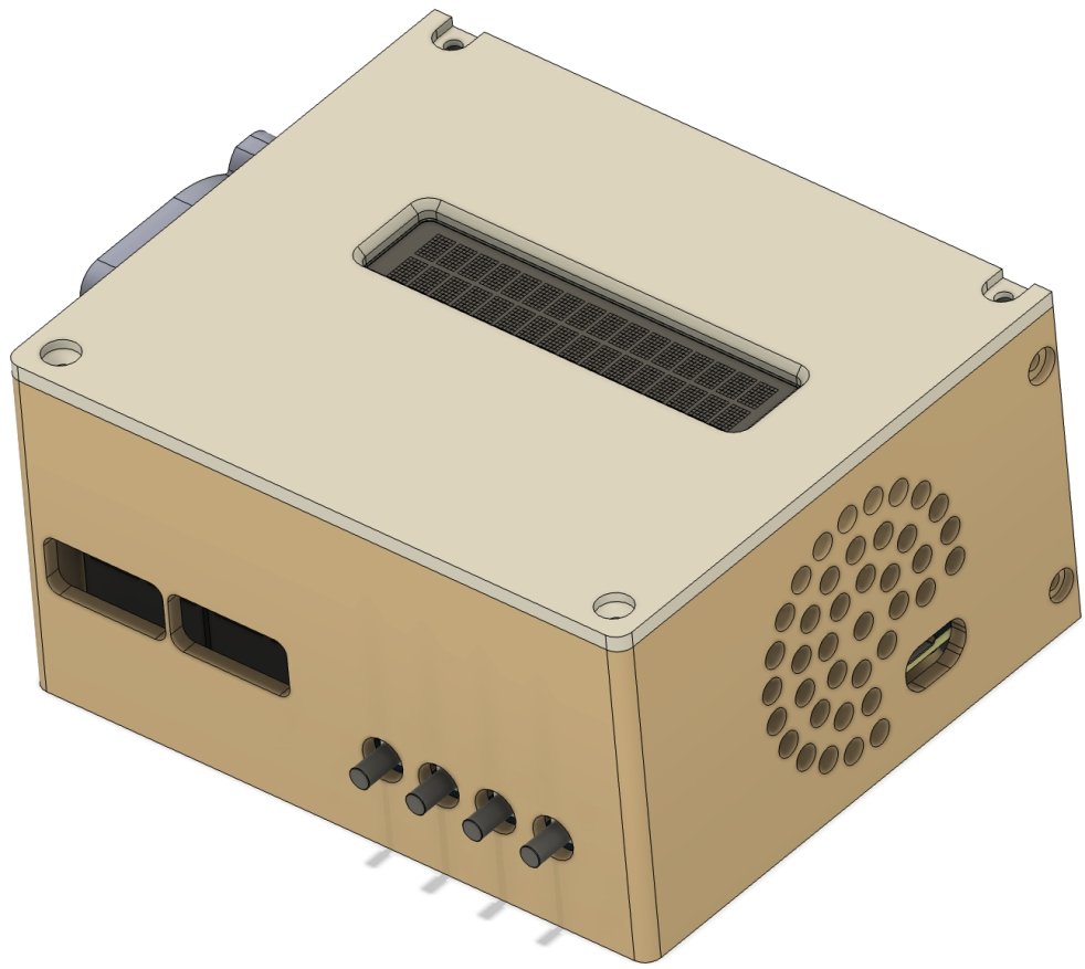
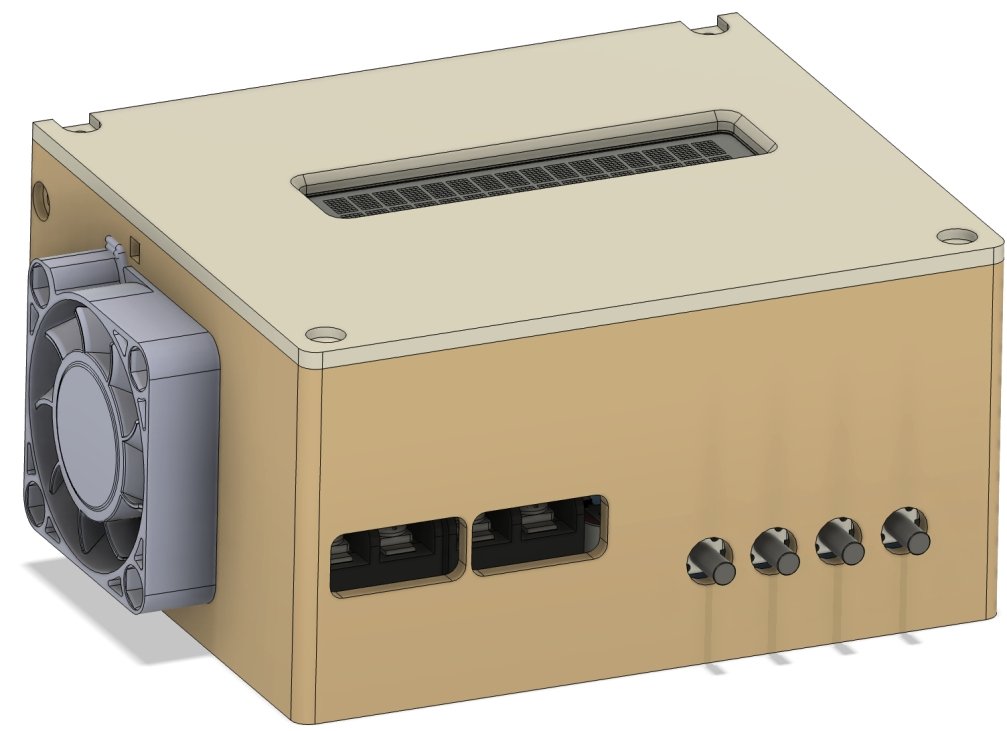
3D Printed Enclosure:
As you know, I didn’t use the PCB designed by the original author. Instead, I used a slightly changed version, so I designed an enclosure right for it. So you could download the STL files and print them out if you are able to access a 3D printer. Please note that all the screws used in the enclosure are M3.
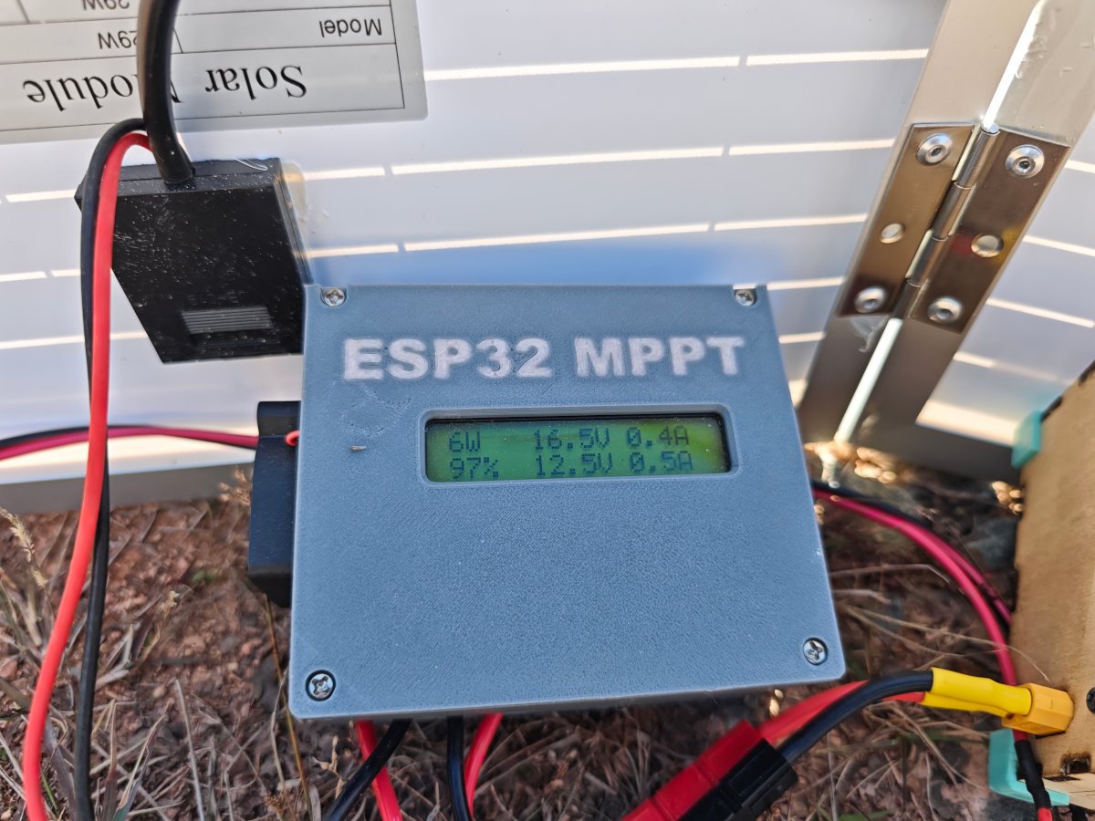
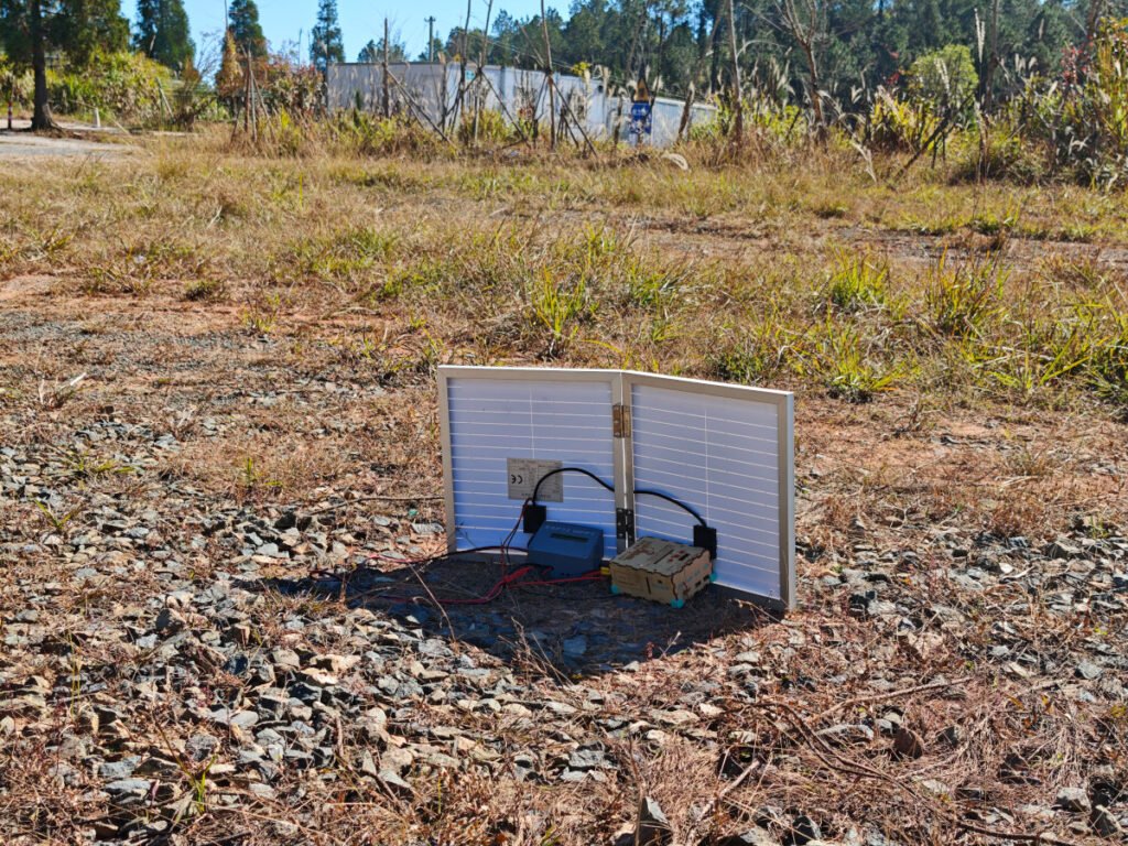
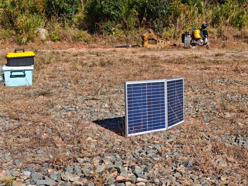
Field Setup:
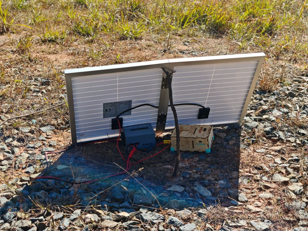
As you could see from the picture, I hooked up my small solar panel(30W/18V) to the input terminal, and connect my LiFePO4(14.4V/20Ah) to the output terminal. The controller has a battery detection feature, once it finds a battery connected, it starts to charge it with the voltage and current parameters configured in the menu settings. I put the controller and my battery just behind the solar panel so that they could enjoy the shade there. I didn’t use a long cable. Why, because a long cable could behave as an antenna radiating the high speed switching current to the air. It can cause a lot of RFIs and blind my radio. I normally bring 2 batteries, in this case, if one battery is run out, I could still use the other one for radio operation. I can charge the dead battery up by the solar system.

The Apps:
1. Blynk
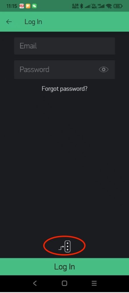
Install Blynk (Legacy) App and load the app. From the main screen, click “Log In”, and on the “Log In” page, touch the icon above the “Log In” bar, this will let you set the custom blynk servers. Click the button to enable the custom blynk server entry. The server could be a IP address of your local area network, or could be a public domain name that could access your blynk server. Then input your account and password on the upper part of the page. If you don’t have an account, you have to go back to the main screen and click ”Create New Account”, but be sure you have input your custom blynk server prior to creating a new account.
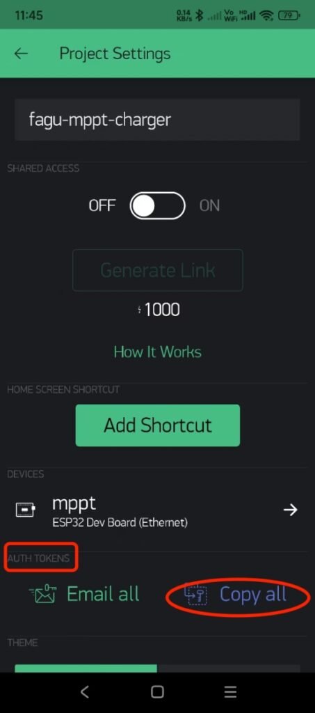
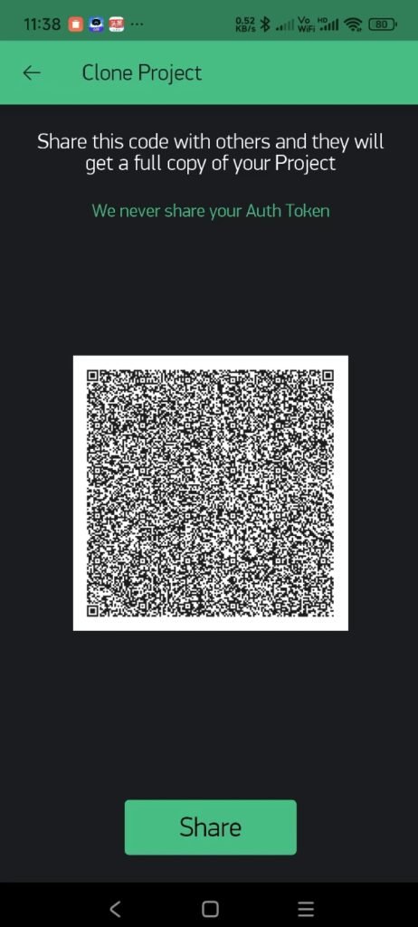
After log-in, touch the QR code icon on the upper part of the page, use your phone’s camera to scan the project’s QR code, and then, the app will make a clone of the project, otherwise you will have to create the project by yourself. From the project page, touch the configuration icon to enter the project settings page. On that page, go to the “AUTH TOKENS” and touch “Copy all” to copy the token strings. You have to paste the token to somewhere in the arduino code. The “Email All” function does not work for me, or perhaps for private or custom blynk servers either.
The app will display all the real-time parameters once the controller hardware connects to your custom blynk server successfully. Be sure to use the correct token, have your code compiled and successfully uploaded to your MPPT controller. You need to enable the WiFi feature (menu settings) on the controller side too.
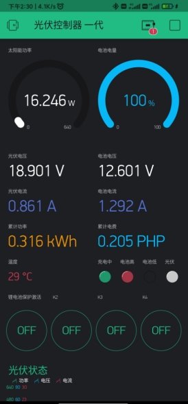
2. Blinker
The Blynk App is good enough for somewhere with WiFi and Internet Access. It though supports BLE, it’s still in beta test, you will see the notice if you load a BLE example code. So I decided to use Blinker App as an instead for outdoor/field purpose, where there is no way to have a WiFi access point and Internet.
From your MPPT controller, in the menu settings, disable “WiFi” feature, then restart the controller by disconnecting and connecting the solar panel or your lab power supply to the Input terminal. It now works at BLE mode.
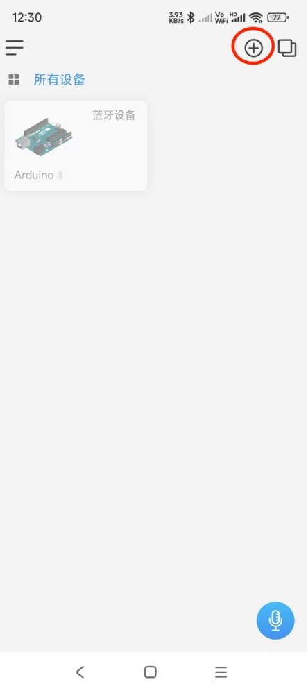
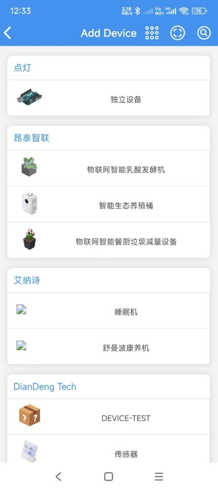
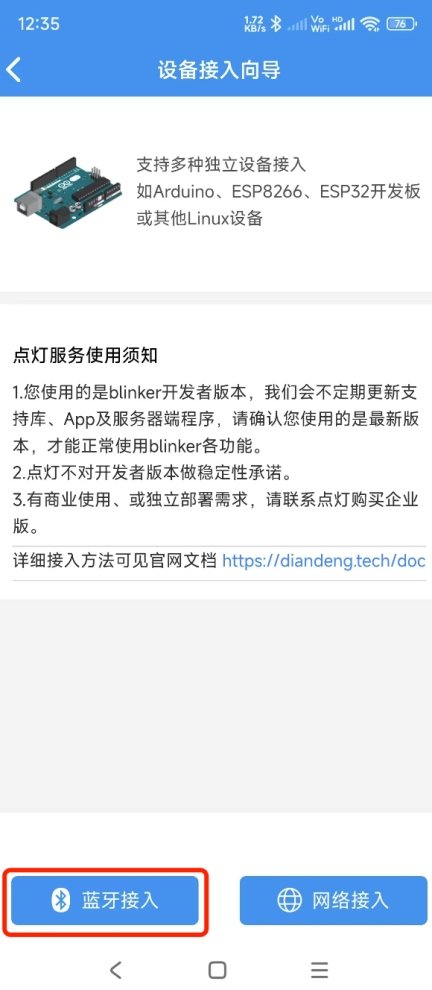
Install the Blinker App, and load it. From the main screen, click to add a device. Next, select the Arduino board on the top. The App supports two kinds of connections, blue-tooth and WiFi, here we need to click the “Bluetooth”, see the picture below, it doesn’t matter if you don’t understand Chinese. It then will try to communicate with your MPPT controller by BLE.
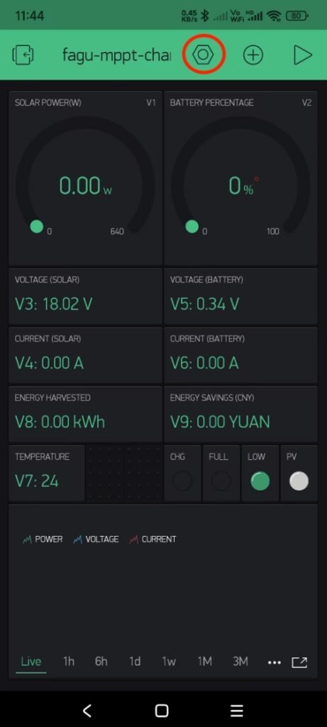
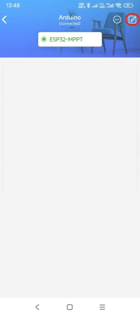
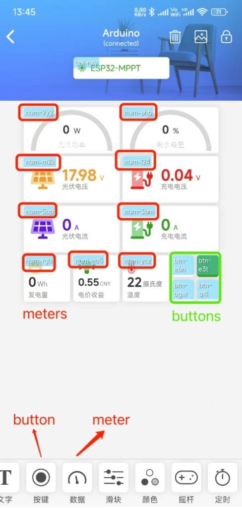
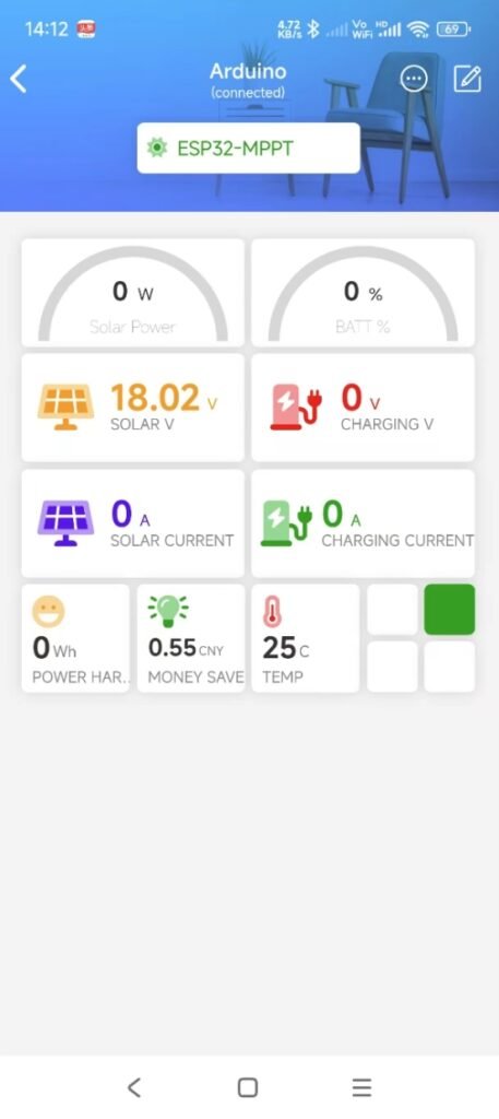
From the project page, click the icon on the upper right corner. Next, you have to place widgets on the page, there are many widgets on the bottom, but for this project, we just use two kinds of widgets, meter and button. Pay attention to the strings in red or green rectangle, please keep them the same as here, otherwise you have to use your name string (like an ID) in the widget to replace the ones used in the Arduino code. Keep them unchanged unless you know what they are. The widgets in the green rectangle are buttons. The final dashboard is as the following. The settings in the App are Chinese, but it doesn’t matter, just play it, you will succeed then.
Possible Interferences and Solutions:
An MPPT (Maximum Power Point Tracking) controller can potentially cause radio frequency interference (RFI) to ham radio due to several technical factors. MPPT controllers use switching regulators (e.g., DC-DC converters) to optimize power transfer from solar panels to batteries. These regulators operate by rapidly switching high-frequency currents (normally in the kilohertz (kHz) to megahertz (MHz) range). The fast switching action produces harmonic frequencies (integer multiples of the base switching frequency). These switching signals mostly are PWM (Pulse Width Modulation) signals, they are non-sinusoidal signals composed of a fundamental frequency and an infinite series of harmonic frequencies (odd and even multiples of the fundamental). Higer-frequency PWM signals (e.g., 100 kHz) generate harmonics that extend deeper into the HF (3–30 MHz) and even VHF (30–300 MHz) ham bands. These harmonics act as unintended RF transmitters. If any harmonic falls within a ham radio’s receive frequency (e.g., 7 MHz for the 40m band or 14 MHz for the 20m band), it can directly interfere with signals or create background noise. If your antenna is near the MPPT controller or its cables, the antenna may pick up the controller’s RF emissions as unwanted noise.
To reduce RFI from an MPPT controller:
- Shield the controller: Put the controller into a metal box to block radiated emissions.
- Filter power cables: Add RF chokes, ferrite beads, or LC filters to its power cable both on input and output side to suppress high-frequency noise.
- Use shielded cables: Replace unshielded power/control wires with shielded twisted-pair cables, grounded at one end by grounding spike.
- Relocate equipment: Move the MPPT controller and its cables away from the ham radio setup (ideally >10 feet).
Project Files:
https://drive.google.com/file/d/1Tyl4el6wvgdIKGylNReguJ_TP6XggZiB/view?usp=sharing