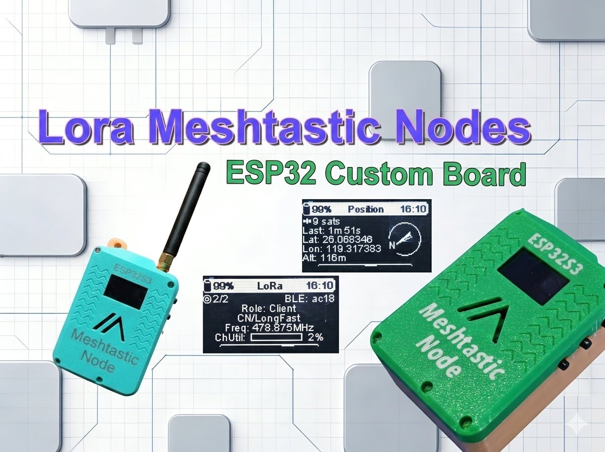
This article details how to build a fully custom Meshtastic LoRa mesh node from zero. It covers open‑source PCB design, component assembly, firmware compilation, 3D printed enclosure, and final configuration for off‑grid, long‑range communication.
Overview
Meshtastic is an open-source communication protocol that transforms affordable LoRa (Long Range) radio modules, typically powered by “ESP32” or “nRF52” microcontrollers, into a secure, off-grid, and decentralized mesh network capable of sending encrypted text messages, GPS coordinates, and other data over long distances without relying on Wi-Fi, cell towers, or satellites. In this self-healing system, every Meshtastic device acts as an automatic repeater, forwarding messages from one node to the next until they reach their destination, effectively extending the network’s range far beyond the line-of-sight of any single device, making it an ideal solution for off-grid adventure, emergency preparedness, or communication in remote areas.
Meshtastic primarily uses the license-free, sub-gigahertz (sub-1 GHz) frequency bands allocated for LoRa radio technology, which are highly region-specific due to local telecommunications regulations. Using the correct frequency for your location is mandatory for legal compliance and to communicate with the local mesh.
Primary Regional Frequencies
| Region Code | Description | Frequency Range (MHz) | Typical Operating Frequency |
| US | United States, Canada, etc. | 902.0 – 928.0 MHz | Default Slot: 906.875 MHz |
| EU_868 | European Union, UK, etc. | 869.4 – 869.65 MHz | Default Slot: 869.525 MHz |
| EU_433 | European Union (Lower Band) | 433.0 – 434.0 MHz | Default Slot: 433.875 MHz |
Other Common Frequencies
- China (CN): 470.0 – 510.0 MHz
- Japan (JP): 920.8 – 927.8 MHz
- Australia/New Zealand (ANZ): 915.0 – 928.0 MHz
- India (IN): 865.0 – 867.0 MHz
- 2.4 GHz (LORA_24): Some Meshtastic devices can use the 2400.0 – 2483.5 MHz band, which is a worldwide license-free band, though it generally offers shorter range than the sub-GHz bands.
Meshtastic Hardware
A traditional Meshtastic node consists of the core and optional components on a single circuit board to create the off-grid mesh communication platform. The core components are essential for running the Meshtastic firmware and transmitting data.
Core Components: They are microcontroller unit (MCU), LoRa radio transceiver and an antenna. The mcu is the “brain” that runs the meshtastic firmware, handles encryption, manages data, and controls all other components. The lora radio transceiver is the dedicated chip that sends and receives data packets over the LoRa radio frequency bands. A detachable antenna is connected to the LoRa chip via a SMA or IPEX connector. A properly tuned antenna is critical for maximizing range and should always be attached before powering the device to prevent damage to the radio chip.
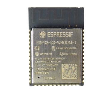
- An ESP32S3 module works as the brain of the meshtastic node. There are other MCUs that could work with the meshtastic, e.g. modules with nRF52840, raspberry Pi Pico W.
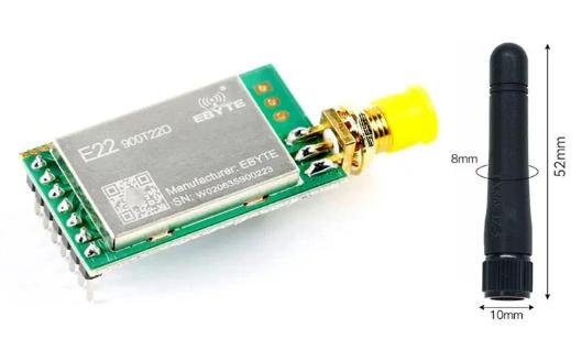
- A LoRa Radio module is used for sending and receiving data in a meshtastic network.
Optional Components: There are other components in a meshtastic node, and we call them optional or peripheral components. These components add user interaction and utility to the node. For example, the power management parts handle the power control of the unit or even the solar charing. A GPS could be integrated into a meshtastic node for providing the location information. An OLED/LCD display can be used to display the node’s status, IDs, battery life, and received messages. Some commercially made meshtastic boards even have some buttons used for scrolling through information pages.
Building A Meshtastic Node
Meshtastic is kind of open source hardware, with tons of tutorials and documents. It certainly has no difficulties to build one by yourself. A general building process is like this, you buy a commercially made MCU board with LoRa radio integrated, like Heltec(e.g., V3) or Lilygo (e.g., TTGO T-Beam). Next, you flash the board with meshtastic firmware. You can do it directly on the web page of meshtastic.org. Then, you install the Mobile App, connect your meshtastic node via bluetooth and do some basic configurations. Finally, you could install the node into a 3d printed case or other enclosures that you have. All the process are pretty simple and straight forward.
Building A Customized Meshtastic Node
A customized meshtastic node is a bit different from those commercial boards. You could customize the components on the board, also the shape of your board. However, you need a high-level of electronic knowledge to design the PCB and have it manufactured and assembled later. In the following contents of this article, I am going to show you how I build a customized meshtastic node from scratch.
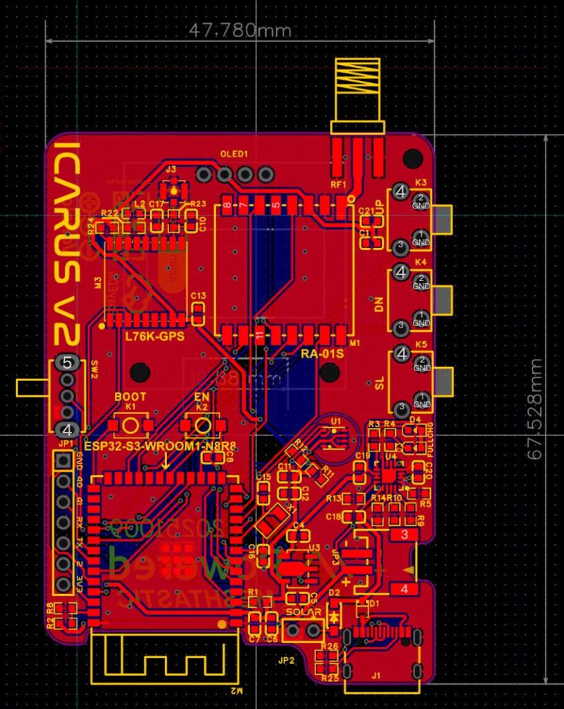
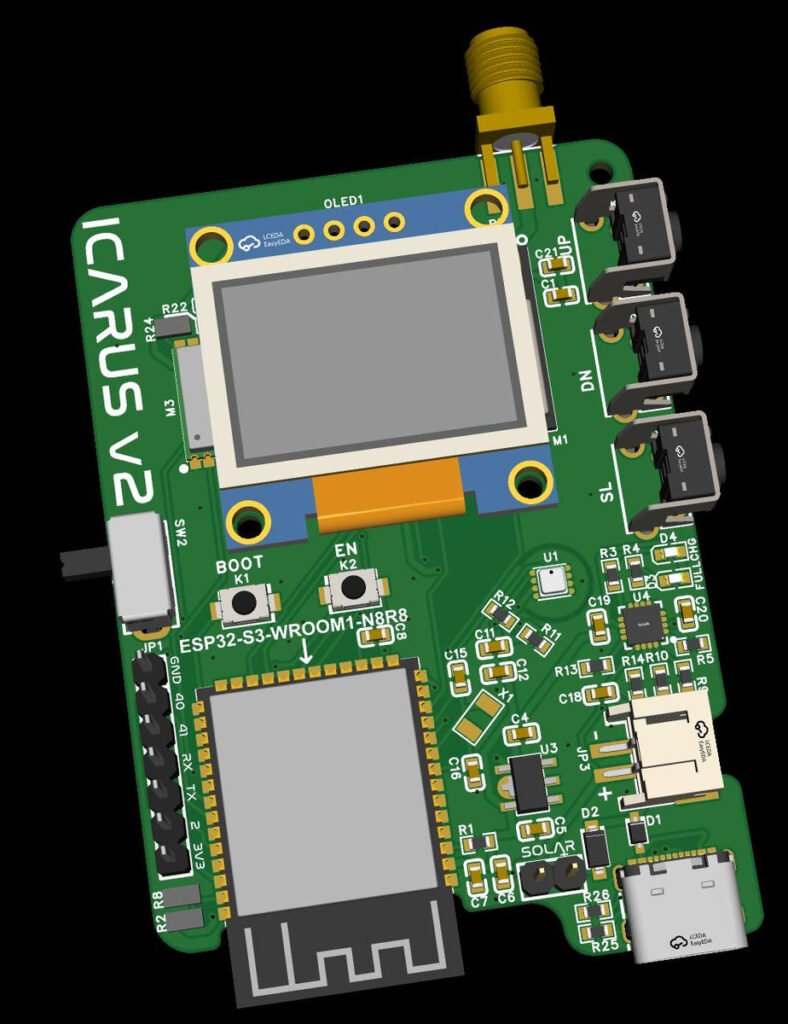
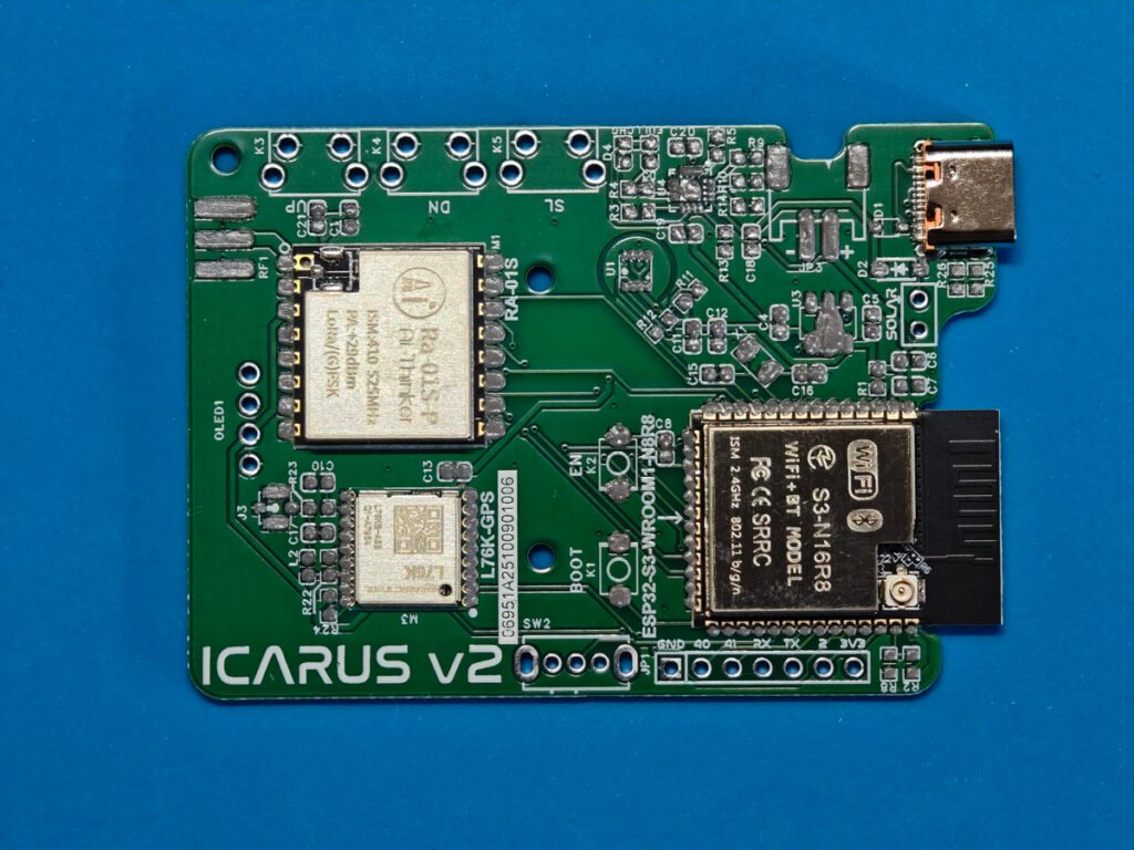
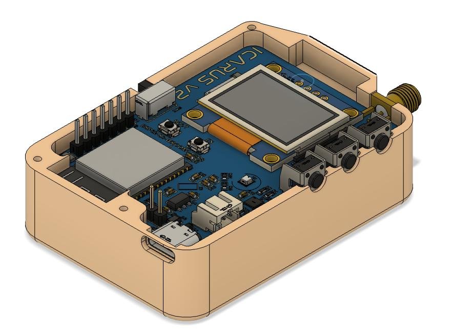
As the meshtastic is an open soure project, you could find many non-commercial designs from makers over the internet. The one I used is called Icarus-v2, which is a functional meshtastic board integrating GPS and bme280 for position report and environmental data telemetry.
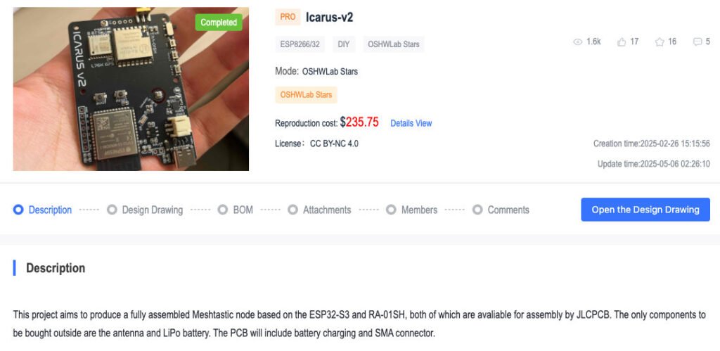
I refined the board with some parts I could easily access, and finally I had my own version of icarus-v2 ready.
1. Schematic description, how it works?
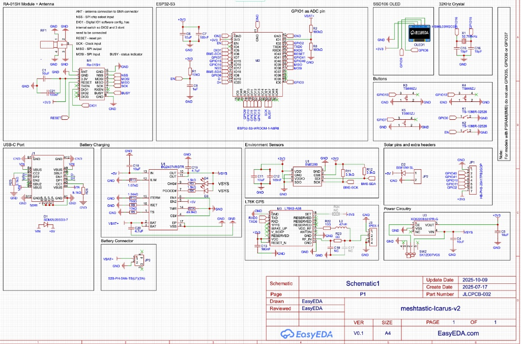
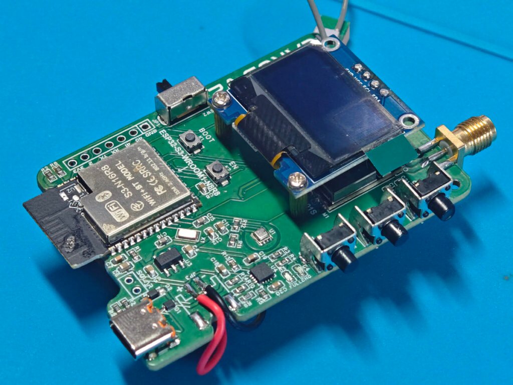
As you could see, the board is driven by the ESP32-S3 microcontroller, which acts as the system’s central brain. The ESP32 manages all data flow, connecting to your phone via Bluetooth for user control and interfacing with the Ra-01SH (SX1262) LoRa radio via SPI to handle long-range transmissions. When you type a message from your phone or when the L76K GPS and BME280 sensor collect location and environmental data, the ESP32 processes this information and commands the radio to broadcast it to other nodes in the mesh network.
As for the power management, a 3.3V voltage regulator and a battery charging IC BQ24074 support these core functions. This circuit ensures the device can run autonomously, charging a lithium battery from USB or solar power and stepping that voltage down to a safe level for the other electronic parts. Finally, the user interface—consisting of three GPIO-connected buttons and an I2C OLED screen—allows users to view messages and configure settings directly on the device. The pinout map is as the following:
| Component | Function | ESP32-S3 Pin (GPIO) | Notes |
| LoRa Radio | NSS (CS) | 38 | Chip Select |
| (Ra-01SH) | MOSI | 36 | SPI Data |
| MISO | 35 | SPI Data | |
| SCK | 37 | SPI Clock | |
| BUSY | 34 | Radio Status | |
| DIO1 | 33 | IRQ / Interrupt | |
| RESET | 39 | Radio Reset | |
| I2C Bus1 | SDA | 8 | Used by OLED |
| SCL | 9 | Used by OLED | |
| I2C Bus2 | SDA | 18 | Used by BME280 |
| SCL | 6 | Used by BME280 | |
| Buttons | UP | 12 | Active Low (Needs Internal Pullup) |
| DOWN | 13 | Active Low (Needs Internal Pullup) | |
| SELECT | 7 | Active Low (Needs Internal Pullup) | |
| Power | Battery ADC | 1 | Voltage Divider (100k/100k) |
| GPS | TX | 43 | GPS RX IN |
| RX | 44 | GPS TX OUT |
2. PCB assembly
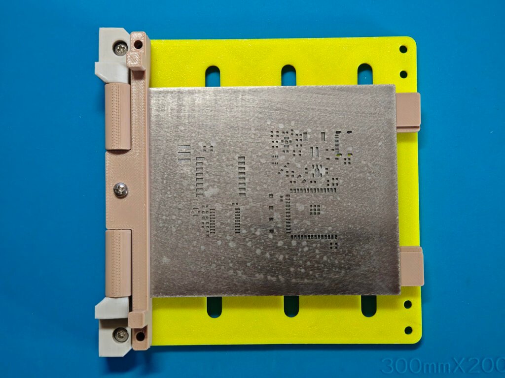
The PCB was made by JLCPCB.COM, and it also came with a stainless PCB stencil for printing the solder paste onto the pcb. The size of stencil is only 10cm x 8cm, I have a 3d printed stencil frame to make the solder paste printing job easy.
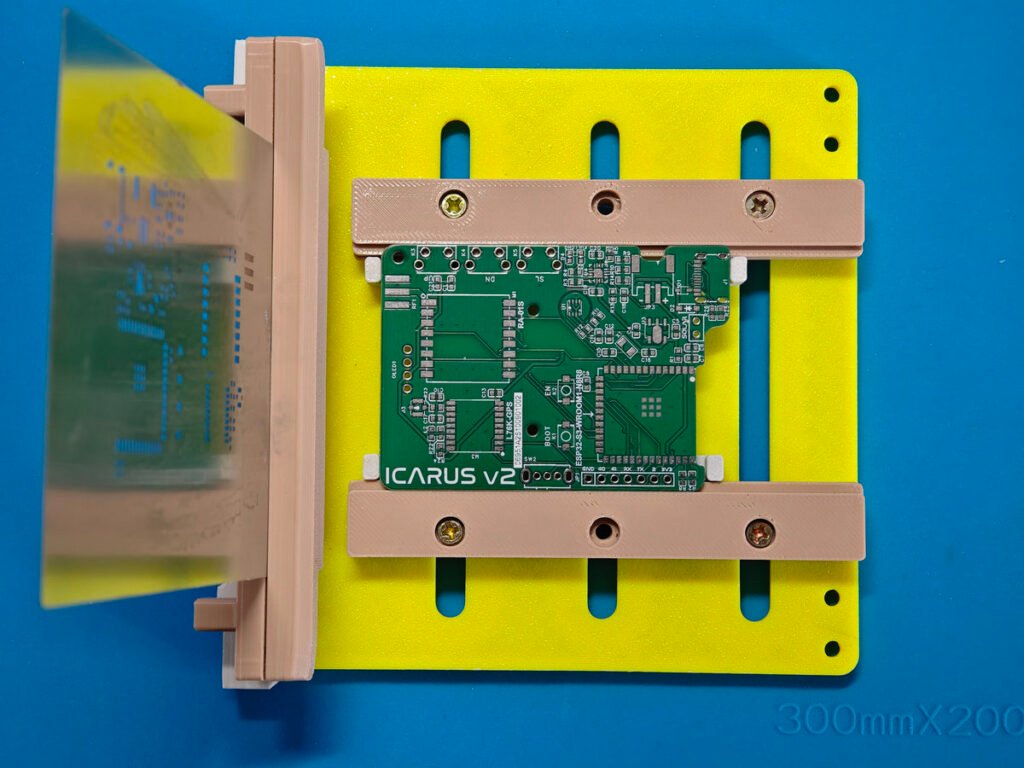
Caption:All SMD components placed on the Meshtastic PCB before reflow soldering
When all of the smd parts are picked and placed, it’s ready to have them soldered. You may see some of the parts are not well aligned, but it’s OK, those parts will be automatically moved on to the right position when being soldered by a reflow heater. The small tiny parts like BME280 and BQ24074 are not installed, as they need to be manually soldered by hand later so as to have a good soldering.
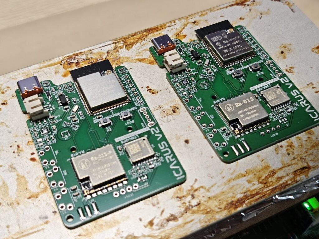
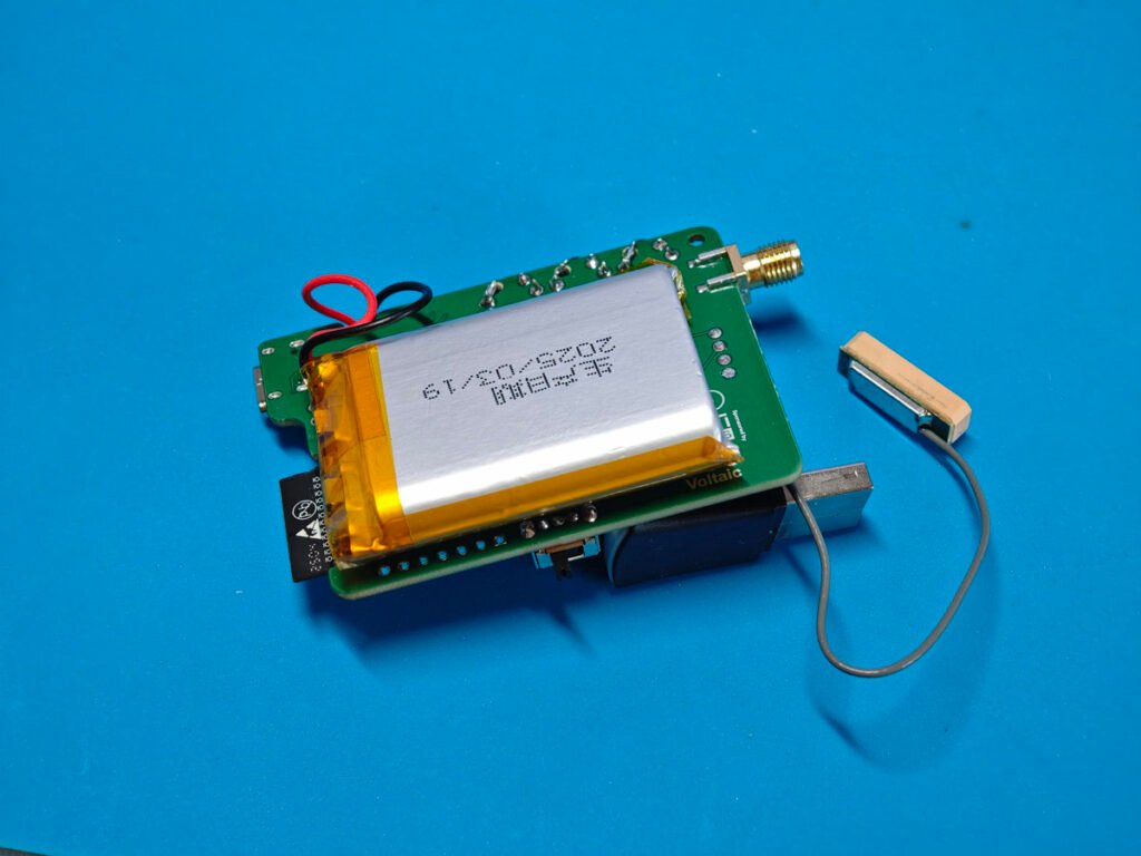
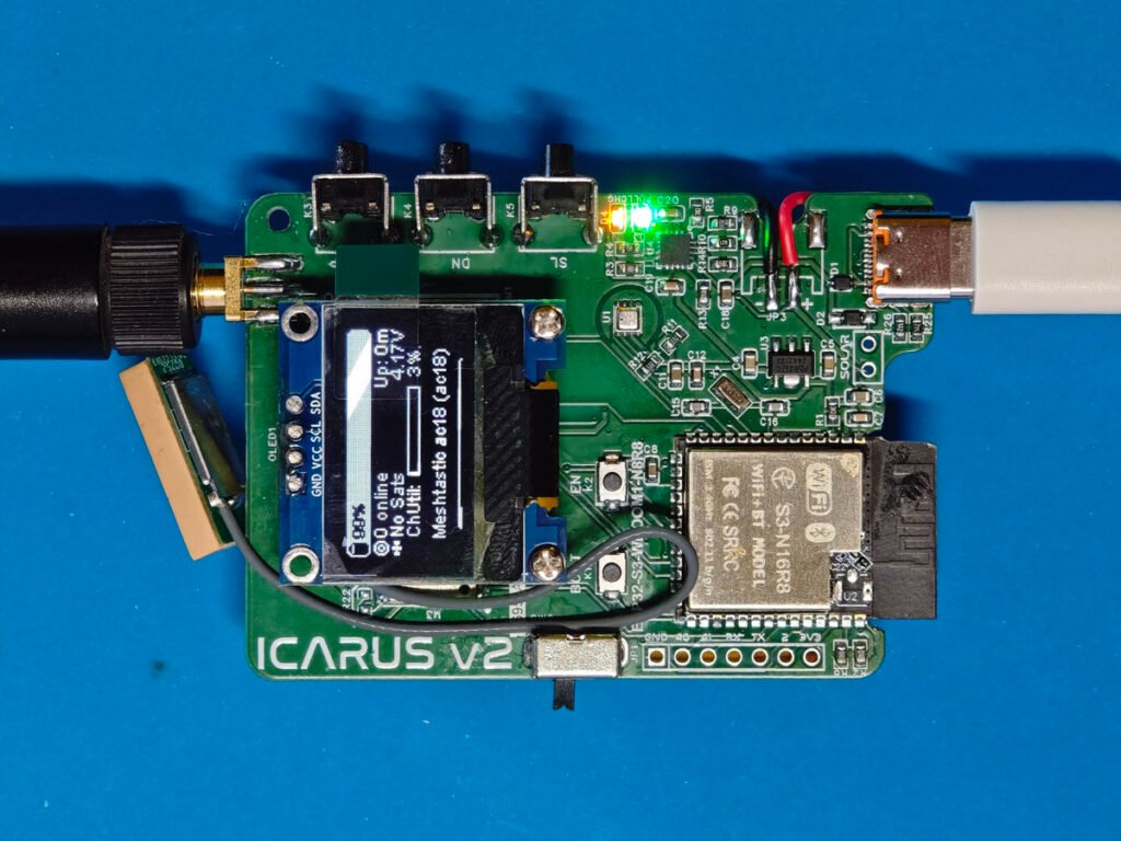
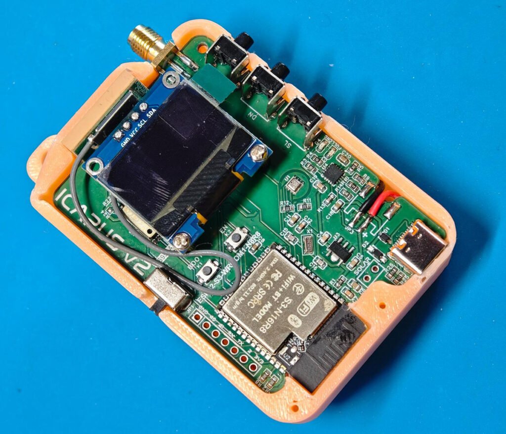
The final board with both the smd and through hole parts assembled, and a lithium battery (2000mAh) is sticked on the back of the board. A gps antenna is also attached to the board. The oled module is mounted by 2 standoffs (M2 x 7)
3. Firmware uploading
This is a customized DIY meshtastic board, therefore there is no ready-made firmware available. You have to download the source code and make the compilation. The source code should be opened by vscode. Make sure you have the platformio plugin installed in your vscode ide.
In order to compile the code smoothly, you have to create your own “board.json” file, and “variant.h” file. I have made those files and you could download it from my google drive. Without these files, you are not able to compile the code successfully.
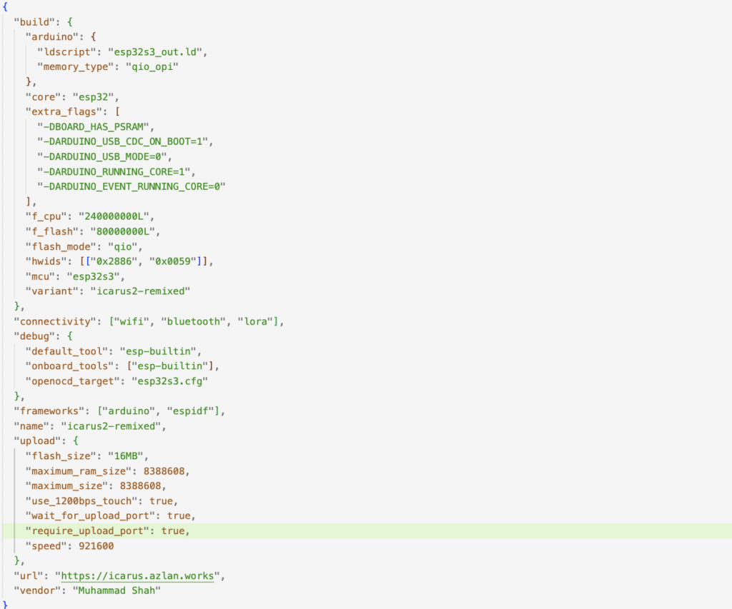
{
  "build": {
    "arduino": {
      "ldscript": "esp32s3_out.ld",
      "memory_type": "qio_opi"
    },
    "core": "esp32",
    "extra_flags": [
      "-DBOARD_HAS_PSRAM",
      "-DARDUINO_USB_CDC_ON_BOOT=1",
      "-DARDUINO_USB_MODE=0",
      "-DARDUINO_RUNNING_CORE=1",
      "-DARDUINO_EVENT_RUNNING_CORE=0"
    ],
    "f_cpu": "240000000L",
    "f_flash": "80000000L",
    "flash_mode": "qio",
    "hwids": [["0x2886", "0x0059"]],
    "mcu": "esp32s3",
    "variant": "icarus2-remixed"
  },
  "connectivity": ["wifi", "bluetooth", "lora"],
  "debug": {
    "default_tool": "esp-builtin",
    "onboard_tools": ["esp-builtin"],
    "openocd_target": "esp32s3.cfg"
  },
  "frameworks": ["arduino", "espidf"],
  "name": "icarus2-remixed",
  "upload": {
    "flash_size": "16MB",
    "maximum_ram_size": 8388608,
    "maximum_size": 8388608,
    "use_1200bps_touch": true,
    "wait_for_upload_port": true,
    "require_upload_port": true,
    "speed": 921600
  },
  "url": "https://icarus.azlan.works",
  "vendor": "Muhammad Shah"
}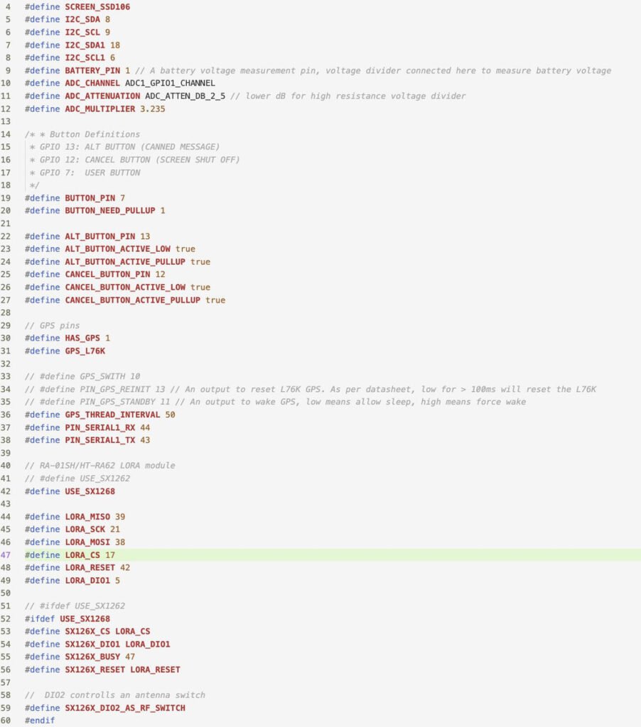
#define SCREEN_SSD106
#define I2C_SDA 8
#define I2C_SCL 9
#define I2C_SDA1 18
#define I2C_SCL1 6
#define BATTERY_PIN 1 // A battery voltage measurement pin, voltage divider connected here to measure battery voltage
#define ADC_CHANNEL ADC1_GPIO1_CHANNEL
#define ADC_ATTENUATION ADC_ATTEN_DB_12 // lower dB for high resistance voltage divider
#define ADC_MULTIPLIER 2.05

/* * Button Definitions
 * GPIO 13: ALT BUTTON (CANNED MESSAGE)
 * GPIO 12: CANCEL BUTTON (SCREEN SHUT OFF)
 * GPIO 7:  USER BUTTON
 */
#define BUTTON_PIN 7
#define BUTTON_NEED_PULLUP 1

#define ALT_BUTTON_PIN 13
#define ALT_BUTTON_ACTIVE_LOW true
#define ALT_BUTTON_ACTIVE_PULLUP true
#define CANCEL_BUTTON_PIN 12
#define CANCEL_BUTTON_ACTIVE_LOW true
#define CANCEL_BUTTON_ACTIVE_PULLUP true

// GPS pins
#define HAS_GPS 1
#define GPS_L76K

// #define GPS_SWITH 10
// #define PIN_GPS_REINIT 13 // An output to reset L76K GPS. As per datasheet, low for > 100ms will reset the L76K
// #define PIN_GPS_STANDBY 11 // An output to wake GPS, low means allow sleep, high means force wake
#define GPS_THREAD_INTERVAL 50
#define PIN_SERIAL1_RX 44
#define PIN_SERIAL1_TX 43

// RA-01SH/HT-RA62 LORA module
// #define USE_SX1262
#define USE_SX1268

#define LORA_MISO 39
#define LORA_SCK 21
#define LORA_MOSI 38
#define LORA_CS 17
#define LORA_RESET 42
#define LORA_DIO1 5

// #ifdef USE_SX1262
#ifdef USE_SX1268
#define SX126X_CS LORA_CS
#define SX126X_DIO1 LORA_DIO1
#define SX126X_BUSY 47
#define SX126X_RESET LORA_RESET

//  DIO2 controlls an antenna switch
#define SX126X_DIO2_AS_RF_SWITCH
#endif
The content of “platformio.ini” file, the file specifies the board being used, which is “icarus2-remixed”. It also specifies the partition space used, which is “default_16MB.csv”, because we use a ESP32S3_N16R8 module in the project.
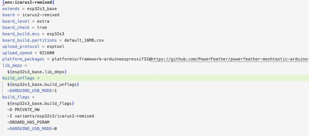
[env:icarus2-remixed]
extends = esp32s3_base
board = icarus2-remixed
board_level = extra
board_check = true
board_build.mcu = esp32s3
board_build.partitions = default_16MB.csv
upload_protocol = esptool
upload_speed = 921600
platform_packages = platformio/framework-arduinoespressif32@https://github.com/PowerFeather/powerfeather-meshtastic-arduino-lib/releases/download/2.0.16a/esp32-2.0.16.zip
lib_deps =
  ${esp32s3_base.lib_deps}
build_unflags =
  ${esp32s3_base.build_unflags}
  -DARDUINO_USB_MODE=1
build_flags =
  ${esp32s3_base.build_flags}
  -D PRIVATE_HW
  -I variants/esp32s3/icarus2-remixed
  -DBOARD_HAS_PSRAM
  -DARDUINO_USB_MODE=0
With these files ready, the compilation is nothing but just clicking the mouse. After firmware flashing is done, take the board to the outdoor, with the GPS antenna connected, it could find the GPS signals within 5 minutes.
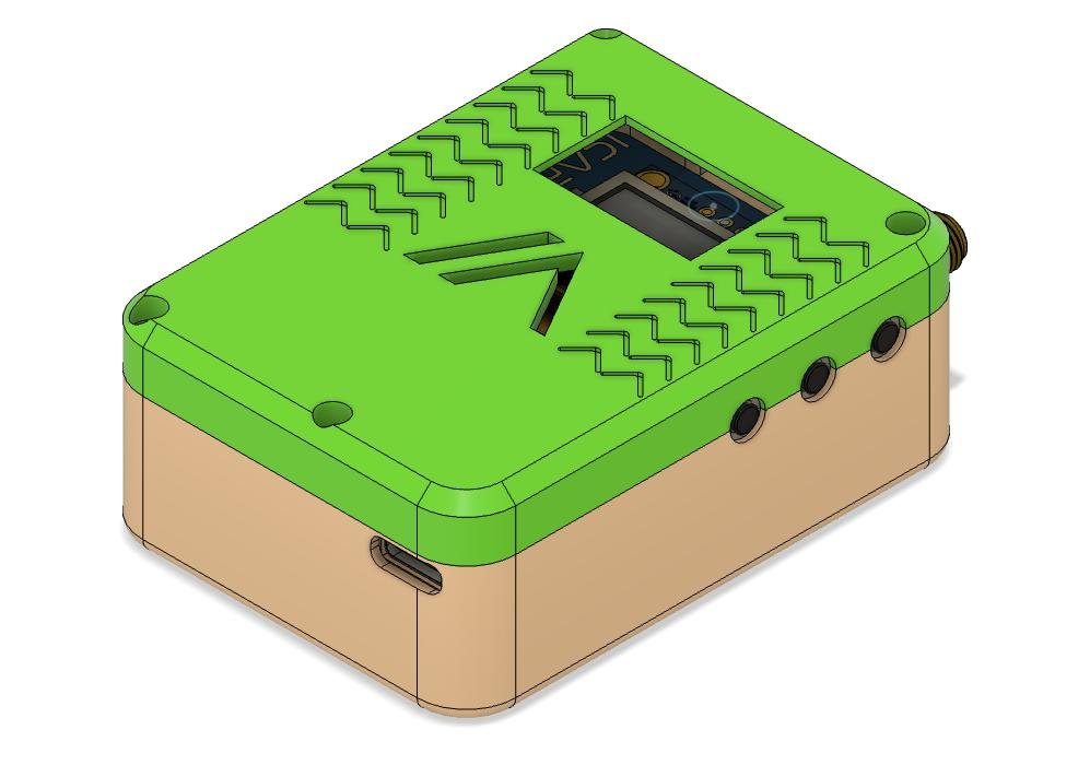
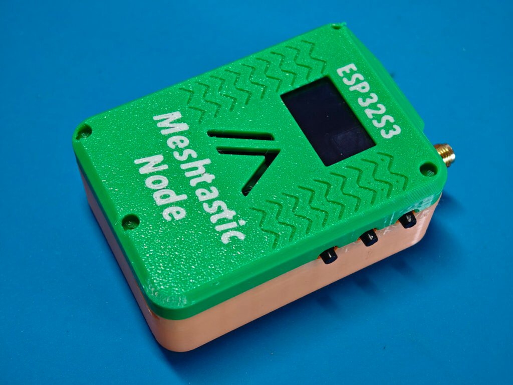
4. 3D printed housing
A 3d printed housing is a must-have option for such kind of project. All files are open source, you could download the original file and have them remixed. The housing features built-in battery, internal room for a GPS antenna. The enclosure is sized in 83.5mm x 53.3mm x28.3mm.
4. Final test
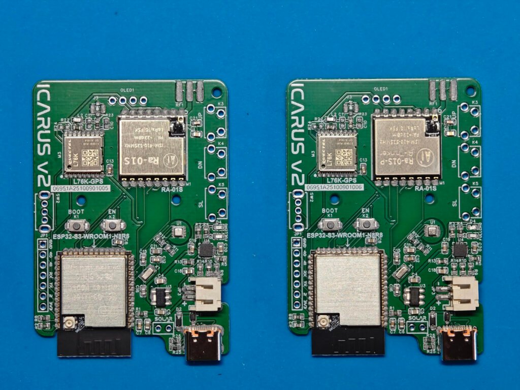
Install the meshtastic app into your phone. From your phone, load the app. Power your meshtastic node now, it should show up the meshtastic logo when starting up. The app will automatically find the existing meshtastic devices and ask for pairing it up. Use the pin code displayed on the OLED to do the pairing. Once the pairing process has been done, the app will automatically connect to your node.
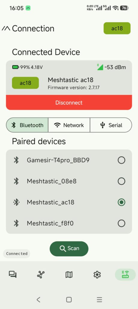
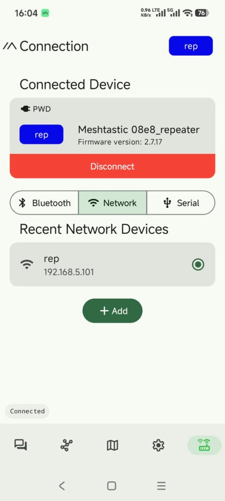
The app has connected to a meshtastic node, the left one is connected via bluetooth, and the other one is connected via wifi. For wifi connection, you have to configure the wifi credentials via the app before making the connection. Initially, for all boards, it should be connected by bluetooth first of all.
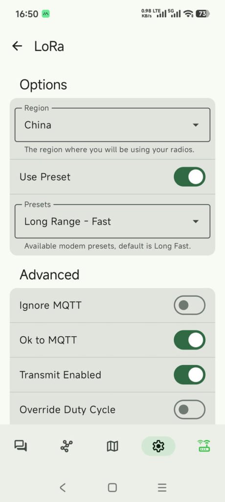
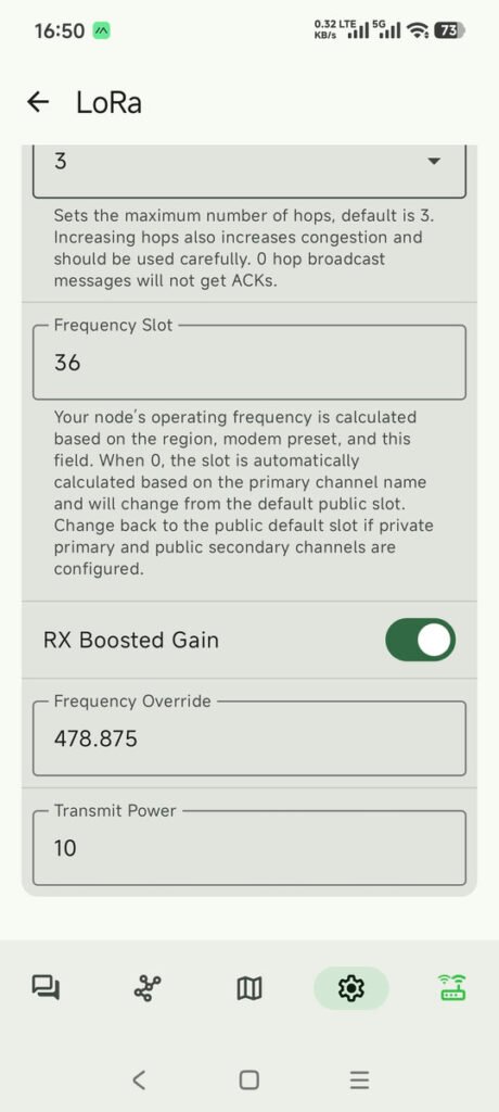
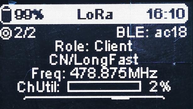
We now have to set the Lora radio before any other settings. From the app, click “setting” tab and in the menu select “LoRa”. Set the Region to your country’s name and use the presets. The “Long Range – Fast” should be the first choice. Scroll down the app, enable the “RX Boosted Gain”. In the “Frequency Slot” field, fill it with the slot number. If you don’t know about it, just fill it with 0. It will automatically calculate the slot number based on your country and the primary channel name.
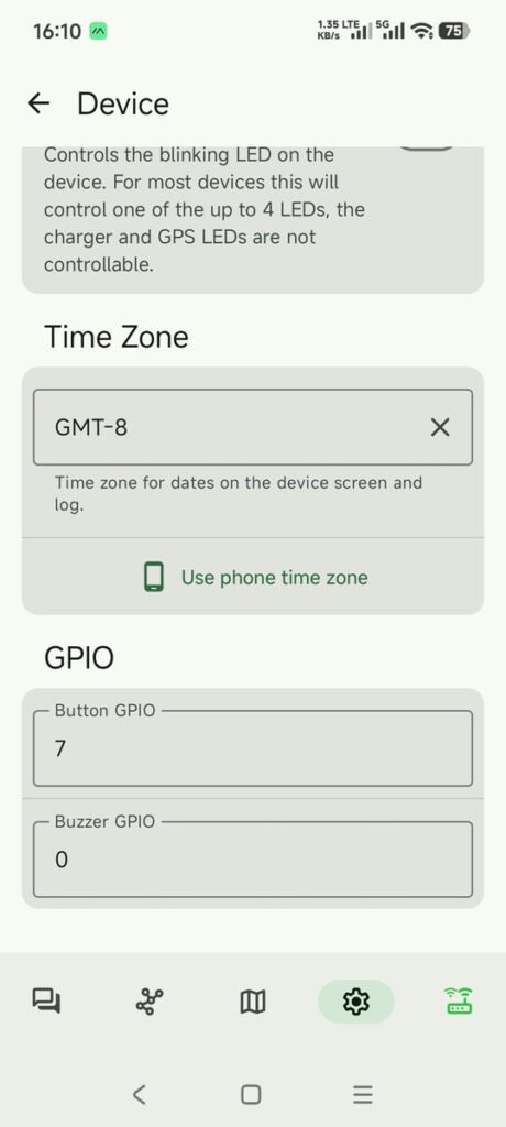
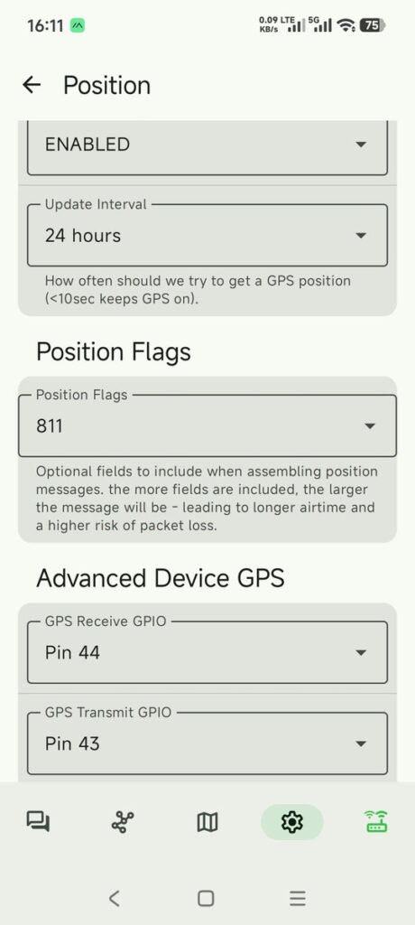
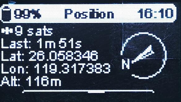
Next, we have to configure the board. In the app, from the setting tab, click “Device”, set your time zone, and GPIO pins for the button. Click the “Position” menu, enable the GPS module, and set the Pin 44 and Pin 43 as the GPIOs to communicate with the GPS module.
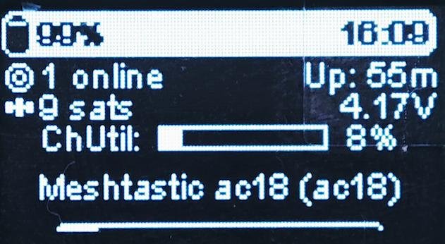
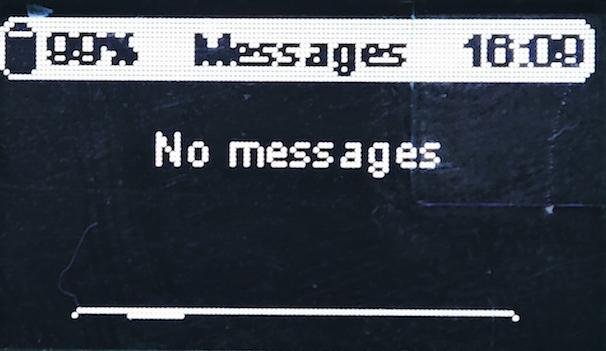
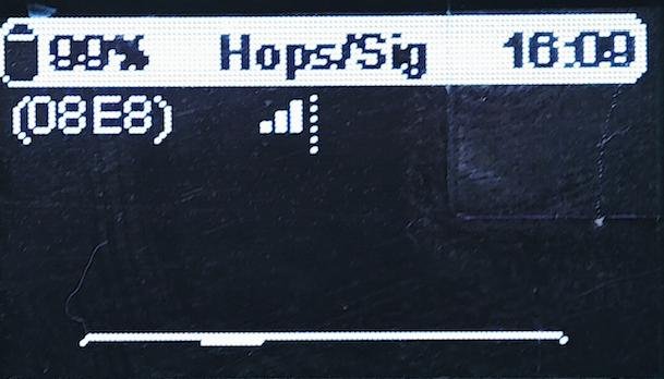
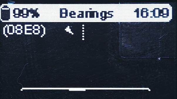
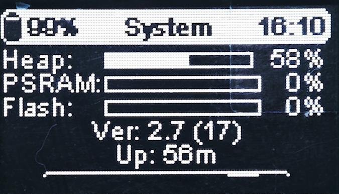
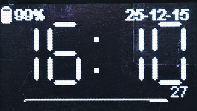
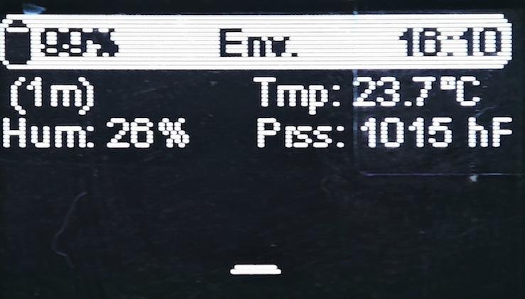
The meshtastic device will be reboot several times while doing these settings. Once things are done, you could test your device by clicking the buttons on your meshtastic board. You could click the first or the third button to scroll the different screens showed on the OLED. Click the middle button to shut off the screen display. Press and hold the third button for up 5 seconds, the device will be shut off. The following are the different screen displays that you could scroll using the first or the third button.
When both of the two boards are properly configured, it’s time to test the message sending and receiving via lora radio. Click the “Conversations” tab on the app, then click channel 0 to do the communication and send the testing messages. From the app, type any words you like, then click “send”. The app will then send out the message by LoRa radio. In your another device, it will prompt up a new message received.
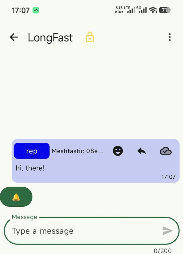
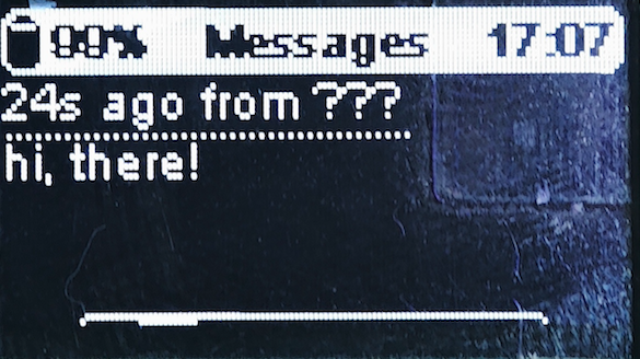
The meshtastic communication from one device to another, with the message being sent from the app that is connected to one meshtastic device.
Project Files:
https://drive.google.com/file/d/14Cc_ZGuEkkVoxUi91nO8eVqClqnDJC2C/view?usp=sharing