
A More Efficient Antenna Is Needed for the Base Station
To improve my Meshtastic base station’s ability to rebroadcast weak LoRa packets, I decided to replace the commercial “rubber ducky” coiled antenna with a homemade J-Pole antenna. While rubber ducky antennas are convenient for handheld devices, they are much less effective for a CLIENT_BASE node. My base station is meant to be the “anchor” for my local mesh, so performance matters more than portability. Below is a comparison between the commercial rubber ducky antenna and the homemade J-Pole antenna.
A. The Radiation Pattern
A standard rubber ducky antenna radiates energy in a roughly spherical pattern with low gain. This means a lot of your precious LoRa signal is wasted by radiating upward into the sky or downward into the ground. A J-Pole, however, has a lower take-off angle and concentrates more of the signal toward the horizon. Since other Meshtastic nodes are likely on the ground or in nearby buildings, the J-Pole sends the energy where it is needed, effectively increasing range without increasing transmit power.
B. Efficiency vs. Compromise
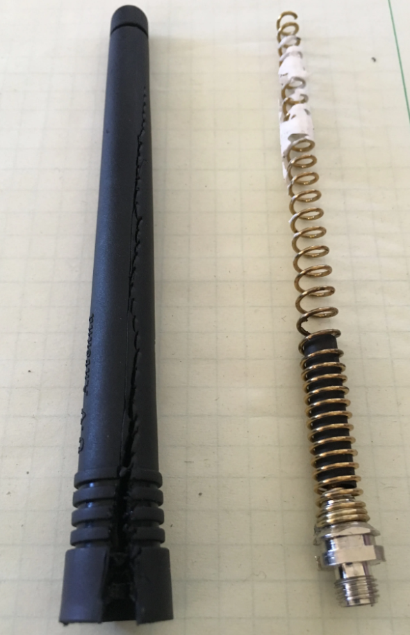
Commercial short antennas are “electrically small.” To make a 490 MHz antenna short enough for portable use, manufacturers often wrap the wire into a tight coil, which acts as an inductor. In my local LoRa setup, the working range is around 470 MHz to 510 MHz.
The Coil Problem: These coils introduce “inductive reactance” and often generate heat. A significant portion of your signal is lost as heat inside the rubber housing.
The J-Pole Advantage: It is a full-sized antenna. There are no lossy coils, so more of the energy from the LoRa module is converted into radio waves.
Precise Tuning for 490 MHz: Commercial antennas are often built for “General UHF” (400-470 MHz) or “70 cm Ham Radio” (430-440 MHz). At 490 MHz, a commercial antenna designed for 433 MHz may have a high SWR (Standing Wave Ratio). This causes power to reflect back into the LoRa module, which can make the radio run hot. By building a J-Pole antenna, we can tune it more precisely for the target frequency. Every antenna also has a usable bandwidth, so an antenna tuned for 490 MHz may still work at 470 MHz or 510 MHz as long as the SWR stays within an acceptable limit, such as below 2.0.
J-Pole Antenna for the Base Station
A J-Pole antenna is an end-fed, omnidirectional vertical antenna that is popular for base stations because it is rugged, simple to build, and does not require a ground plane or radials. Structurally, it looks like the letter “J”. It consists of a half-wave (1/2 lambda) radiator and a quarter-wave (1/4 lambda) matching stub. The stub acts as an impedance transformer, allowing you to feed a high-impedance half-wave element with standard 50-ohm coaxial cable.
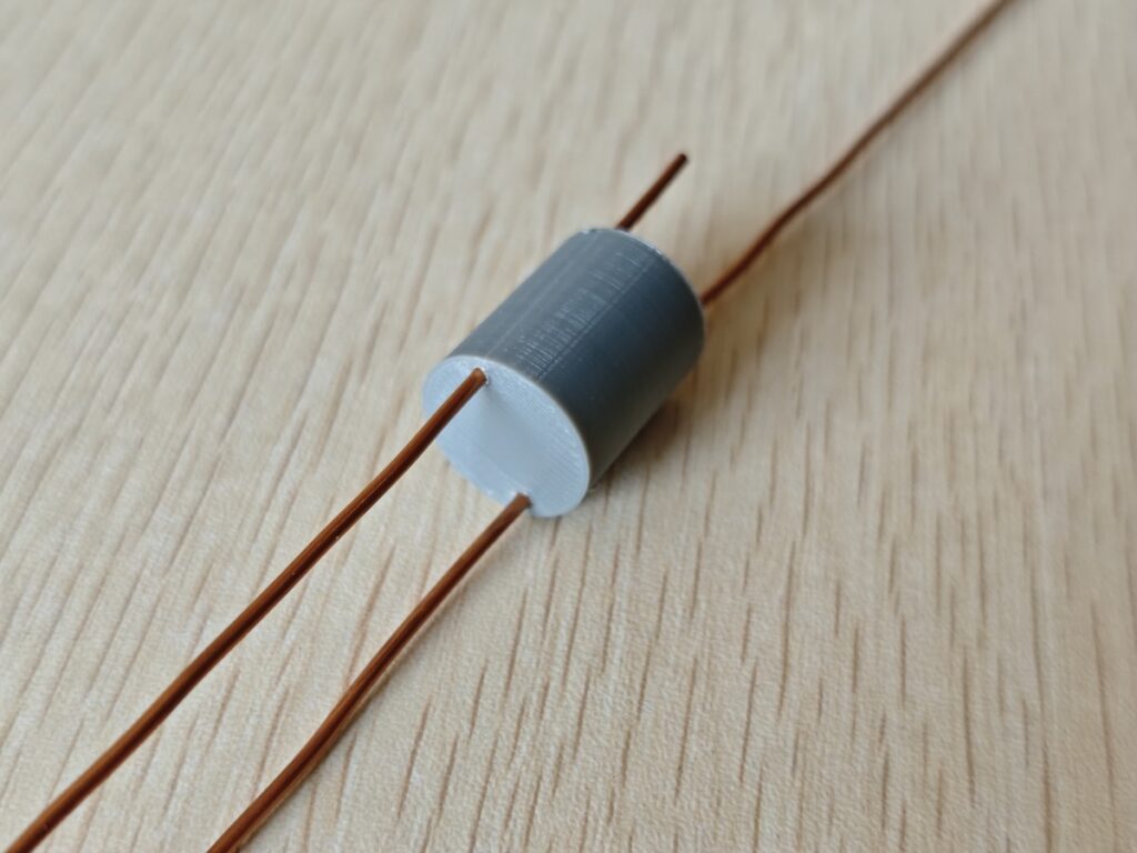
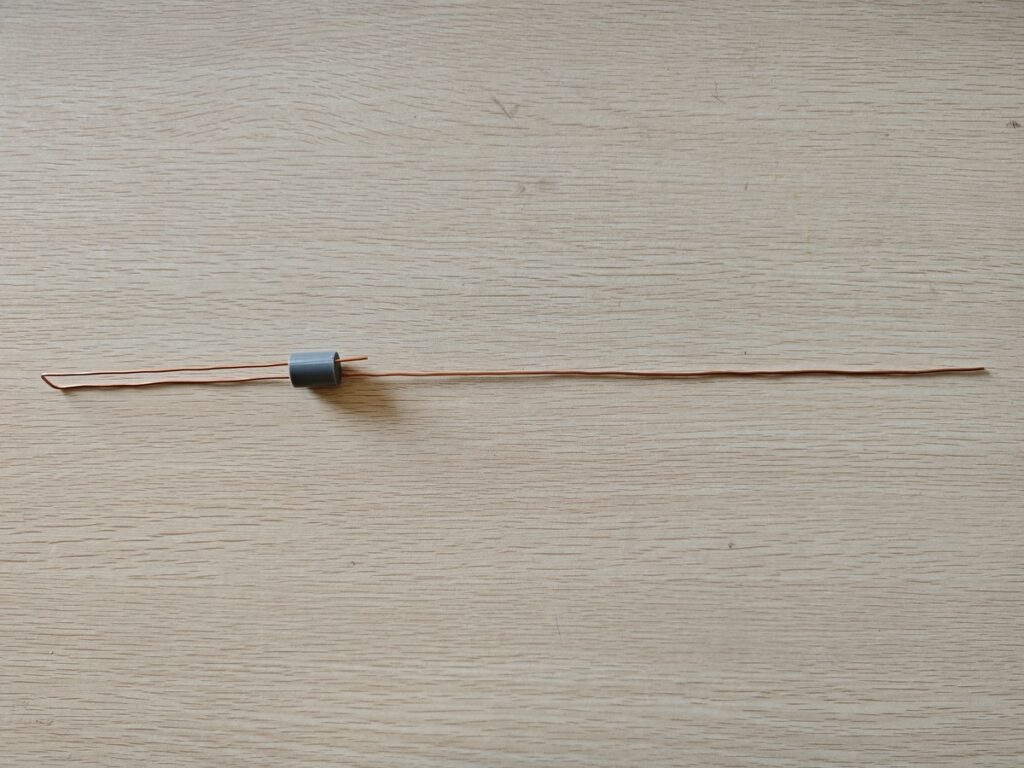
The materials used to build this antenna are easy to find. No special parts are required except for a few 3D printed pieces, such as the PVC pipe cap and the antenna wire spacer. If you do not have a 3D printer, you can replace these parts with other suitable materials. For the antenna radiator, I used a piece of 1.5 mm diameter copper wire. I also used a short, thin coax pigtail with an SMA female connector on one end. To calculate the starting dimensions for the antenna, you can use an online J-Pole calculator.
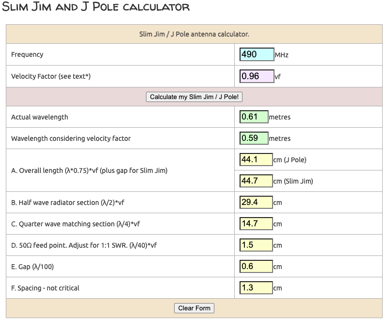
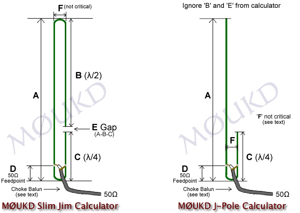
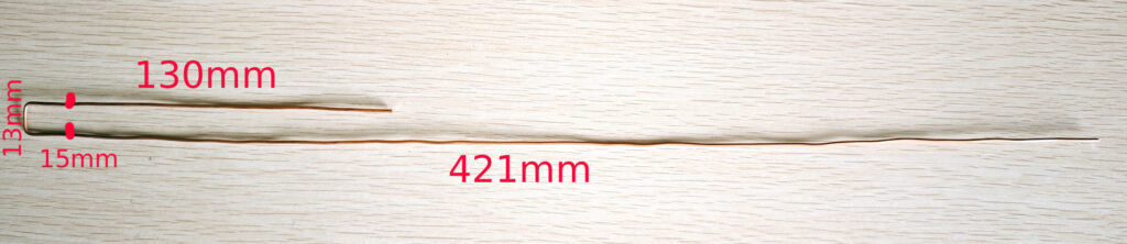
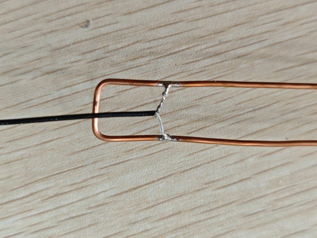
According to the calculated results, cut and bend the wire, then solder the coax pigtail to test the antenna. You will need an antenna analyzer to tune it, and a nanoVNA works well for this job. The image below shows the exact wire lengths I used after tuning. Tuning can be done by adjusting the 1/4 wave stub length and the feed-point position. To move the resonant frequency higher, shorten the 1/4 wave stub. To move the resonant frequency lower, lengthen the 1/4 wave stub.
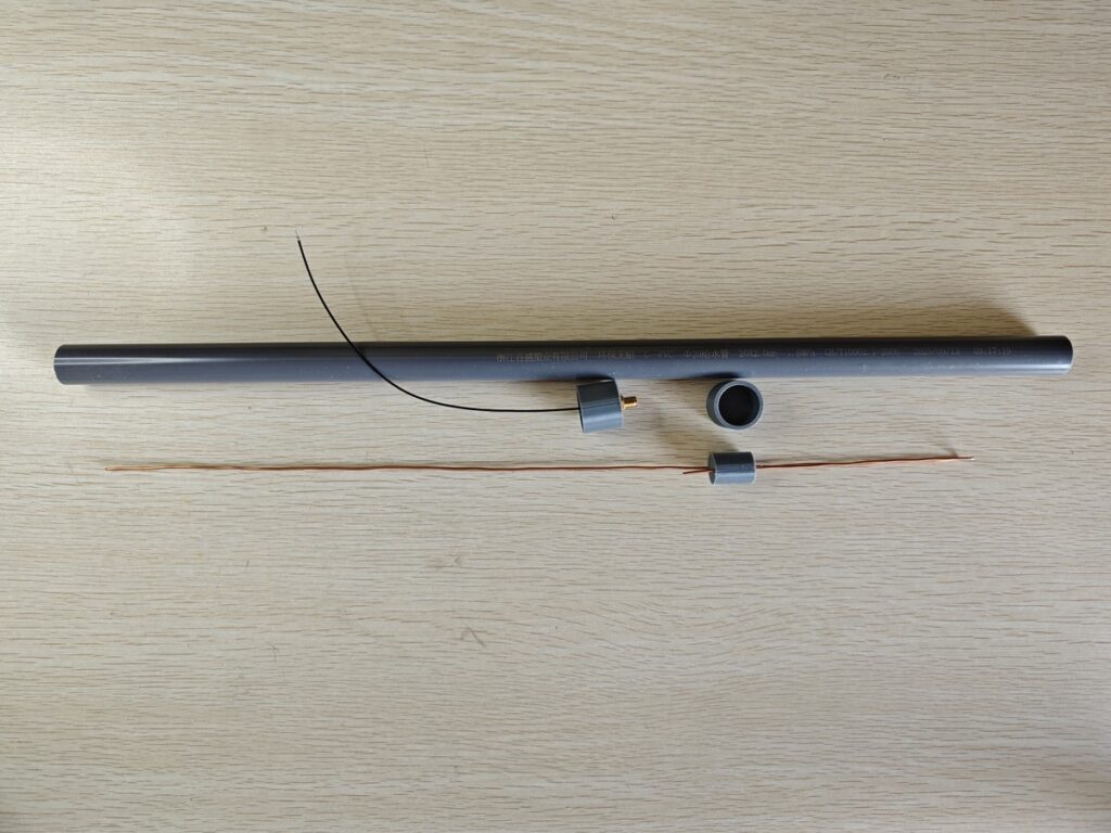
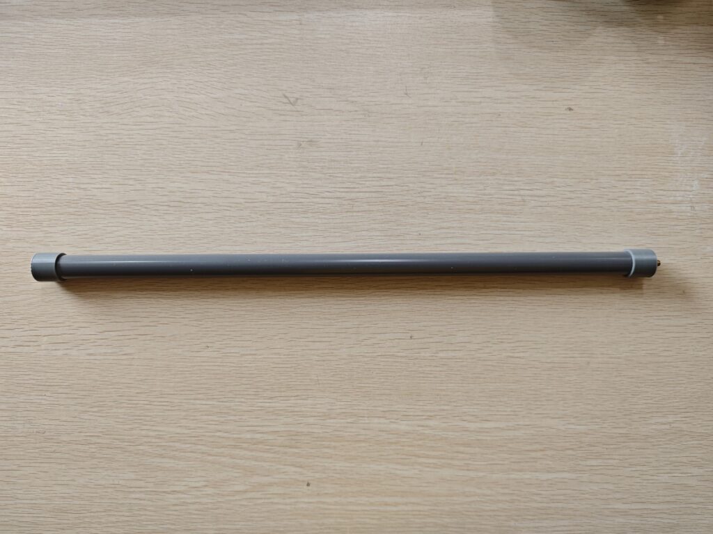
All parts of the homemade J-Pole antenna are shown here. The coax pigtail is mounted on the bottom cap of the PVC pipe.
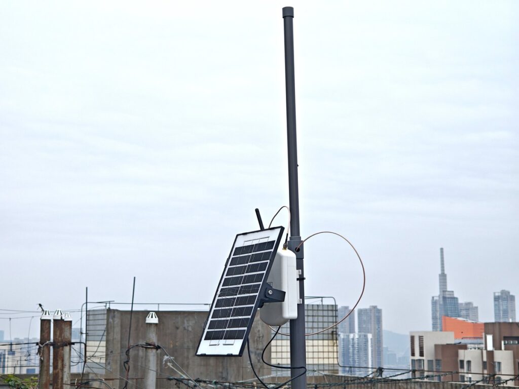
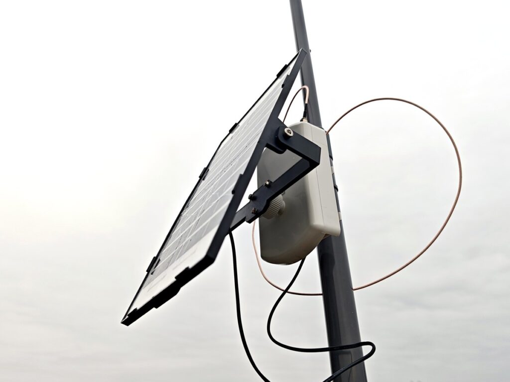
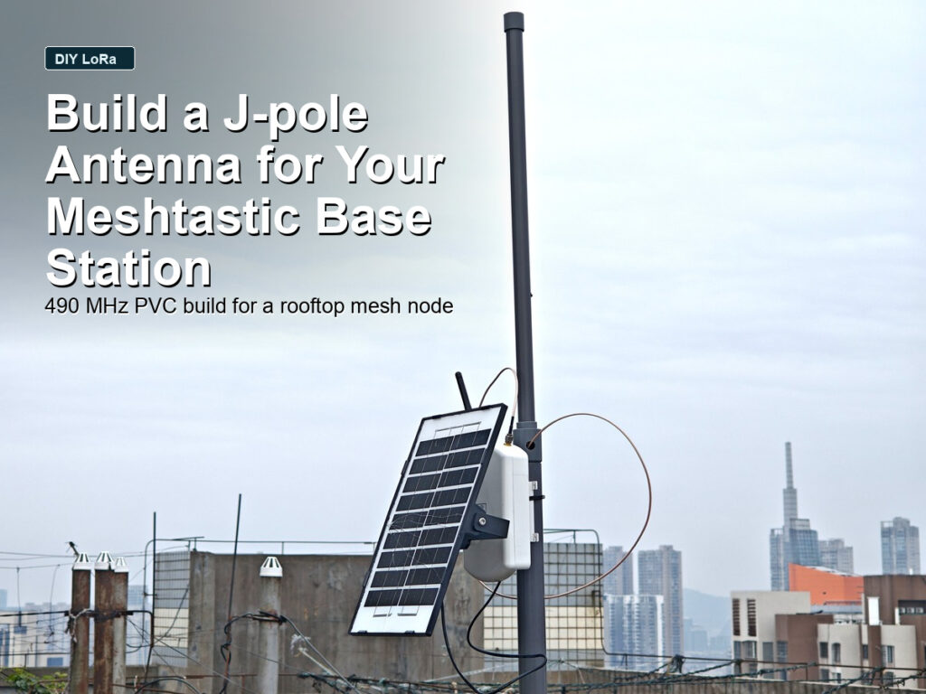
The node was mounted on the roof for testing, with the J-Pole antenna installed behind it at the top of the mounting mast.