Introduction
I got my first ham radio license in 2000, but it was 24 years later before I made my first satellite QSO with a U7V4 cross yagi mounted on my homemade AZ/EL antenna rotator.
For years, I had known how much fun satellite operation could bring to a ham radio operator, but I never liked the usual manual workflow: raising the antenna by hand, pointing it at the satellite, tuning the radio to the correct frequency, and calling CQ. After one or two QSOs, you can already feel exhausted. For low-orbit satellites, this may be acceptable because a pass from AOS to LOS can be 10 minutes or less. For linear satellites, however, the process is more demanding. A pass may last 15-20 minutes, and you need to tune the radio more frequently because of the wider bandwidth and the number of stations working through the satellite.
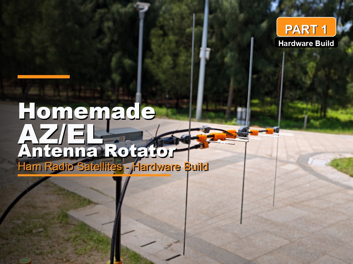
As a result, I did not touch satellite communications for most of my ham radio journey. Then, in 2024, I saw SARCN’s Mini Satellite-Antenna Rotator project and realized it was the right time to build an automatic AZ/EL antenna rotator. I finished my own version three months later, with several differences from SARCN’s design. In this article, I will share the details of my build.
AZ/EL Rotator for Satellite Communications: Working Principles
Before looking at the build, it helps to understand how a typical AZ/EL antenna rotator works for satellite communications, including the hardware, software, communication links, and control protocols.
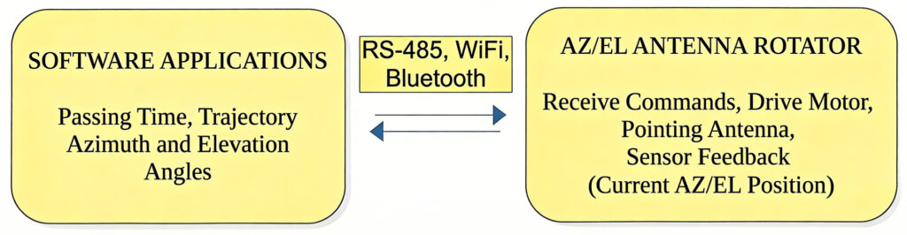
Typically, a software application (e.g., Gpredict, Look4Sat) on your computer or phone predicts the pass timing and trajectory of your designated satellite based on your GPS coordinates. It then converts the calculated tracking data into azimuth (AZ) and elevation (EL) angles to which your antenna (e.g., a Yagi antenna) must point.
The software connects to the AZ/EL rotator through a wired serial connection, often RS-485, or through wireless links such as Bluetooth or Wi-Fi. These links send directional commands to the rotator. All of these connections, whether wired or wireless, belong to the physical layer. Above the physical layer, higher-level protocols such as EasyComm, Yaesu GS232B, and Hamlib Rotctld are used. Through these protocols, the rotator can communicate smoothly with satellite tracking applications running on your phone or computer.
Features:
- Manual or automatic control from a PC or phone. Manual control is also available through the EC-11 encoder.
- The OLED screen displays the current AZ/EL angles and operating status.
- Magnetic encoders are used as angle sensors instead of the 3D position sensor used in the original design.
- Built-in 3S 18650 batteries provide power. The battery board connects to the main controller board through a pair of XT30 connectors, and charging is handled through the USB-C port.
- Connections are available through Wi-Fi or Bluetooth. Wired USB serial is also supported, although wireless operation is preferable.
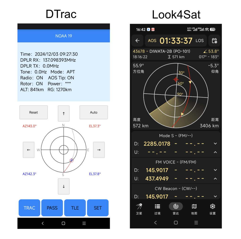
- The rotator works with Gpredict (Rotctld over Wi-Fi), Look4Sat (Bluetooth), and Dtrac (Rotctld over Wi-Fi). It also supports the EasyComm II protocol through a USB serial connection.
Hardware Dive
Core Hardware Parts:
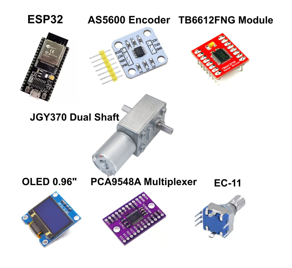
ESP32 Dev Board: The ESP32 is the brain of the controller. I chose it because of its built-in Wi-Fi and Bluetooth capabilities. Unlike SARCN’s design, which uses an additional ESP8266 or Raspberry Pi as a gateway between the wired USB connection and Wi-Fi link, my project lets the ESP32 work as a Rotctld daemon and parse commands sent from a PC or phone through Wi-Fi. Based on its specifications, the ESP32 is powerful enough to handle everything connected to the rotator, so there is no need for another processor. The ESP32 receives AZ/EL data from software applications such as Gpredict or Look4Sat through USB serial, Wi-Fi, or Bluetooth. It then parses the data into target AZ and EL angles for the motors. At the same time, it commands the TB6612FNG module to drive the motors and reads feedback from the AS5600 magnetic encoders to determine the exact position of both the AZ and EL motors. It also drives the OLED display, where all parameters are shown. In manual-control mode, it reads AZ or EL angle input from the EC-11 rotary encoder and moves the motors to the selected position.
AS5600 Magnetic Encoder: Two encoders are used in this project as angle sensors for the AZ and EL motors. Each encoder outputs angle data at 12-bit resolution, which is sufficient for this kind of project. The sensor board is mounted on a bracket attached to the motor. A small round rare-earth magnet is placed on top of the motor shaft, near the center of the chip. The chip detects the magnetic field and reports the angle from 0 to 359 degrees with 0.1-degree precision and 0.4-degree accuracy. It communicates with the ESP32 through the I2C bus. The sensor has one drawback: its I2C address cannot be changed. Since this project needs two AS5600 sensors, and two devices with the same I2C address cannot share one I2C bus directly, a PCA9548A I2C multiplexer is used.
TB6612FNG Motor Driver Module: The TB6612FNG is a dual-channel motor driver module based on MOSFET H-bridge technology, making it significantly more efficient and compact than older bipolar-based drivers such as the L298N. It can independently control two bidirectional DC motors or one bipolar stepper motor. In this project, one TB6612FNG module drives both the AZ and EL motors. Its control logic is simple and similar to the L298N.
OLED Display (I2C) Module: This is a regular 0.96-inch 128×64 OLED display with an SSD1306 controller. It is a compact, high-contrast screen commonly used for text, sensor data, and simple graphics in DIY electronics. The screen shows the antenna’s current AZ and EL positions, the target angles for manual control, and the Bluetooth MAC address when working in Bluetooth mode with Look4Sat.
PCA9548A I2C Multiplexer Board: The PCA9548A is an 8-channel I2C multiplexer, and the TCA9548A is a common alternative. It allows you to connect up to eight I2C devices with the same I2C address, such as multiple OLED displays or magnetic encoders, to a single microcontroller by switching between downstream channels. I use it because the AS5600 magnetic encoder has a fixed I2C address of 0x36.
EC-11 Rotary Encoder: The EC-11 is a mechanical incremental rotary encoder widely used for volume control, menu navigation, and parameter adjustment in electronics. Unlike a potentiometer, it can rotate 360 degrees indefinitely and outputs digital pulses instead of a variable resistance. In this project, the EC-11 is used for manual motor control and menu configuration.
JGY-370 Dual Shaft DC Gear Reduction Motor (0.6 RPM/12 V): The JGY-370 dual-shaft motor is a high-torque DC worm gear motor with self-locking capability and a right-angle output. The dual-shaft design allows one side to drive the load while the other side holds a sensor or encoder.
Other Hardware Parts:
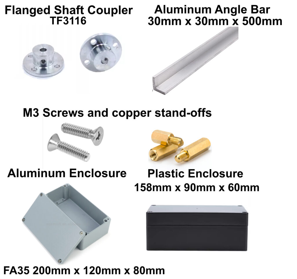
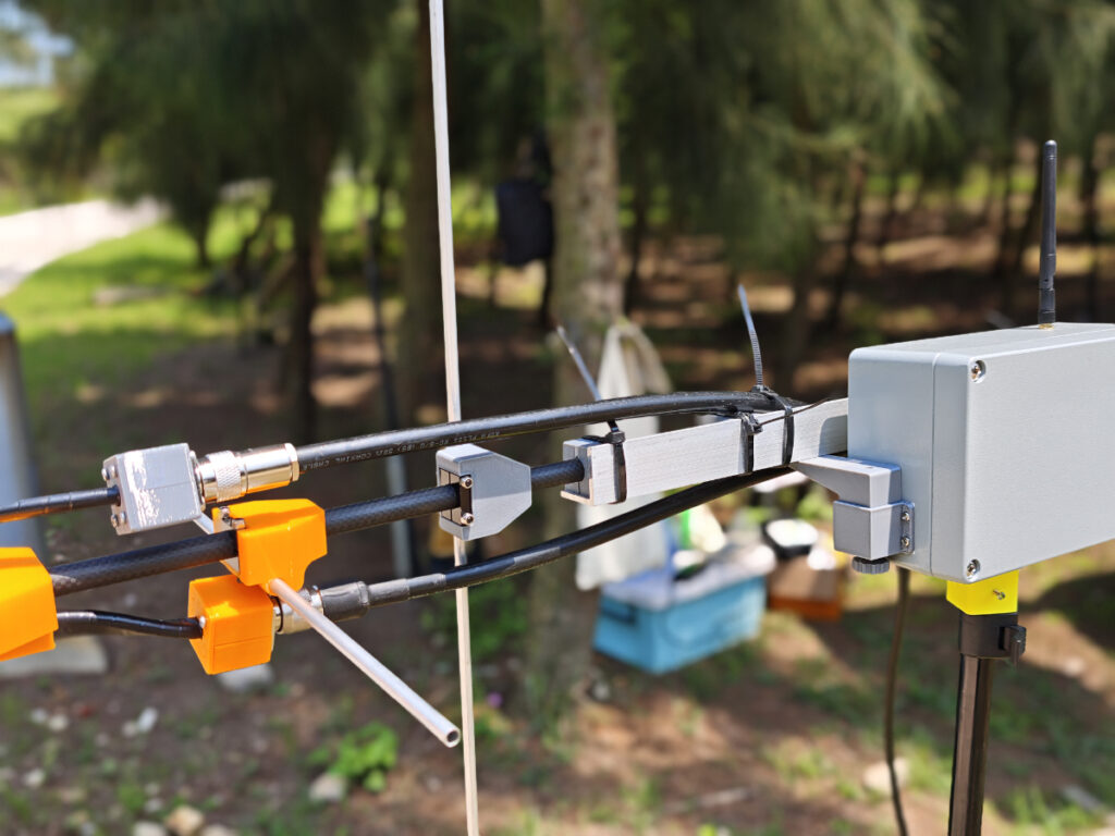
Aluminum Flanged Shaft Coupler (TF3116)**: This rigid connector mounts a rotating shaft directly to a flat surface, such as a wheel, pulley, or gear. It is a good match for the JGY-370 motor because it fits the motor’s standard 6 mm D-shaped output shaft. Two couplers are used in this project: one connects the AZ motor shaft to the tripod, and the other connects the EL motor shaft to the L-shaped aluminum angle bar that holds the antenna in position.
L-Shaped Aluminum Angle Bar (30 mm x 30 mm x 500 mm): The L-shaped aluminum angle bar is the structural backbone that holds the antenna in position. It is lightweight, easy to drill, and provides a rigid 90-degree mounting surface for heavy-duty components.
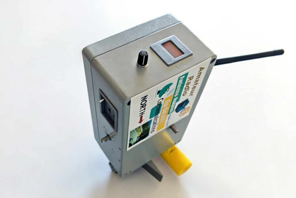
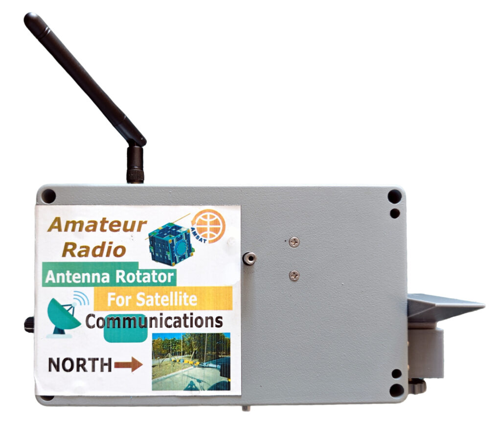
Aluminum Enclosure (FA35 200 mm x 120 mm x 80 mm): The FA35 aluminum enclosure is a heavy-duty junction box designed to protect sensitive electronics in industrial environments. It serves as the rotator housing and holds two motors, two PCBs (main controller and power supply), the OLED display, and the EC-11 encoder. The most difficult part of this project was cutting the windows for the OLED display and the panel mount for USB charging, the USB serial connection, and the power switch. The box is rigid and has a thick wall, so an electric rotary tool such as a Dremel is useful for cutting it.
Alternative Plastic Enclosure (158 mm x 90 mm x 60 mm): A plastic enclosure is an alternative if you do not want to cut windows in an aluminum box. Before cutting and drilling the plastic box, however, the inside should be shielded with copper tape. Otherwise, the rotator may not work properly while the radio is transmitting, especially at higher power levels such as 20 W or 50 W. During transmission, the rotator is exposed to a strong RF field. This RF field can interfere with the AS5600 magnetic sensors and the ESP32, causing them to stop working or behave incorrectly. Even with shielding, you may still hear some noise in full-duplex operation when working linear satellites.
M3 Screws and Copper Standoffs: Pan-head M3 x 6 mm screws are used for mounting the PCBs, and countersunk M3 x 6 mm screws are used for mounting the motors to the enclosure wall. M3 x 10 + 6 copper standoffs are used for stacking the PCBs.
3D Printed Parts:
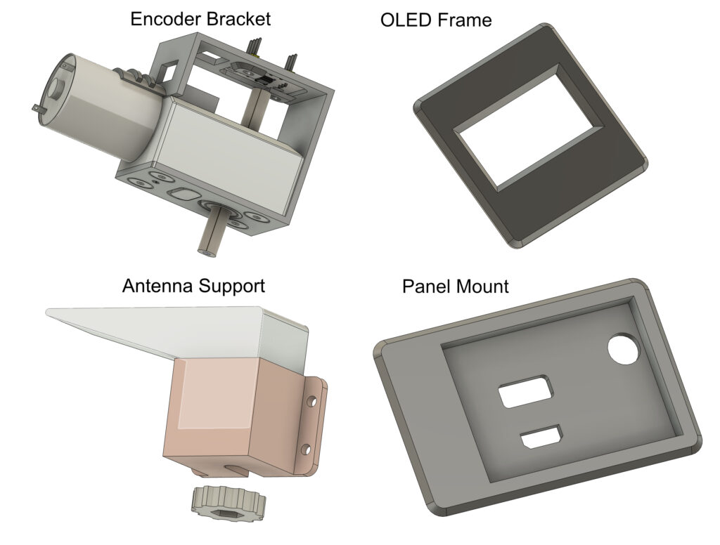
Encoder Bracket: This part holds the AS5600 encoder module. The bracket is mounted on the motor, and the AS5600 sensor is positioned above the end of the motor shaft. A small round magnet is placed on top of the shaft so the sensor can read the rotational angle.
OLED Frame: This part holds the OLED module. The frame is then glued to the rotator enclosure.
Antenna Support: When the yagi antenna is placed horizontally on the rotator, this support temporarily holds the antenna boom and prevents it from dropping if the counterbalance force at the end of the aluminum angle bar is suddenly lost. It also helps protect the motor gearbox in that situation. The support height can be adjusted by turning the nut at the bottom.
Panel Mount: This part is installed at the bottom of the enclosure for the USB charging port, toggle switch, and USB serial port. A window must be cut in the enclosure wall before the panel mount can be installed.
Schematic and PCB:
Main Controller:
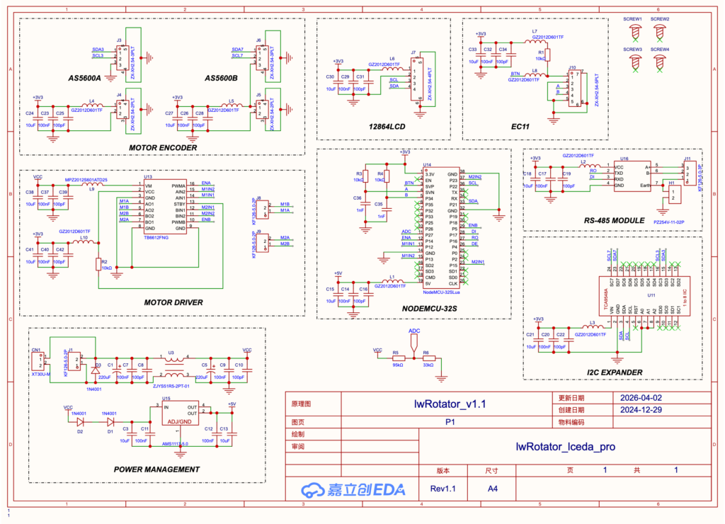
As you see from the schematic, the design is fairly simple. The ESP32 (NodeMCU-32S) is the brain of the system. It controls the TB6612FNG motor driver and receives live AZ and EL angle readings from the two AS5600 modules through the I2C bus. For each motor, three control signals go from the ESP32 to the TB6612FNG module: ENA/ENB, M1N1/M2N1, and M1N2/M2N2.
Because the AS5600 sensor has a fixed I2C address, a PCA9548A I2C multiplexer is used to manage three I2C devices: two AS5600 modules and one 0.96-inch OLED screen. For wired communication with a PC, an RS-485 module is connected to GPIO17, GPIO16, and GPIO4. Other communication options include USB serial, Wi-Fi, and Bluetooth. The EasyComm II protocol is emulated in the firmware over both RS-485 and USB serial. The EC-11 rotary encoder connects to GPIO34, GPIO36, and GPIO39.
The unit receives power from the 3S 18650 battery board through CN1, an XT30 connector. The power then passes through a common-mode transformer (ZJYS51R5-2PT-01) to reduce interference. Next, the VCC voltage is reduced slightly by two 1N4001 diodes and then applied to U15, an AMS1117-5.0 regulator. The regulated 5 V output powers the ESP32 module, and the ESP32 module provides the regulated 3.3 V rail used by the other modules on the board. To reduce noise, a ferrite bead is used in each power chain.
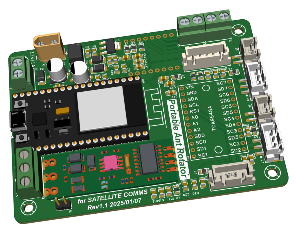
This is the 3D PCB view of the controller board. To make assembly and replication easier, the design uses several ready-made modules. These inexpensive modules are available from Amazon and AliExpress. The PCB measures 95 mm x 70 mm. The four XH2.54 connectors at the top are for the AS5600 sensor modules, and the two connectors on the left and right sides of the TCA9548A module are for the EC-11 rotary encoder and OLED display. J8 and J9 are for the AZ and EL motors. Power enters through the XT30 connector. Jumper H1 is reserved for shielding in RS-485 communication, but I have not tested RS-485 during a real satellite contact, and it may still be affected by interference. In my QSOs, I usually use phone applications, so a wireless connection is preferable.
Battery Board:
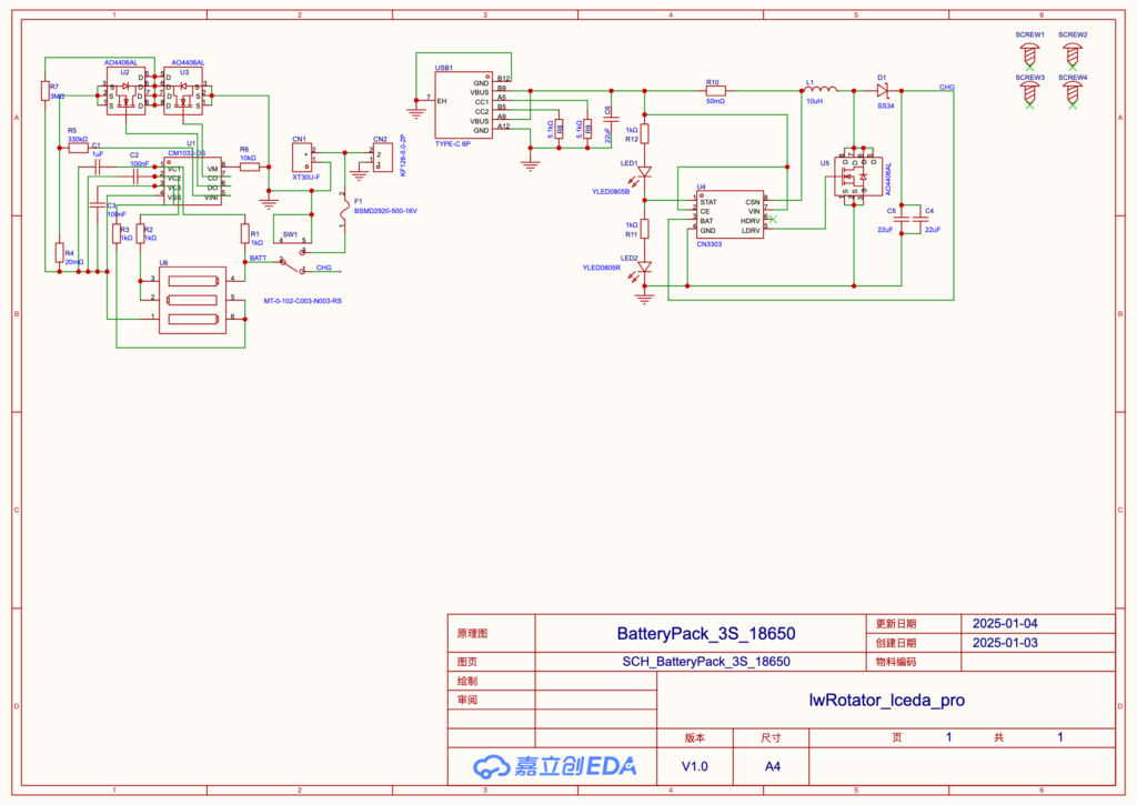
The circuit shown above implements a 3-cell (3S) 18650 lithium-ion battery pack designed as a portable power source for the satellite antenna rotator. It consists of two core functional blocks: a battery-protection circuit and a USB-C-based boost charging circuit. On the left, the CM1033-DS protection IC monitors the 3S battery pack. It uses resistive voltage dividers (R1-R3) to monitor individual cell voltages and controls dual AO4406AL MOSFETs (U2, U3) for charge and discharge path management. This setup provides protection against overcharge, over-discharge, overcurrent, and short-circuit conditions while helping to keep the cell voltages balanced.
The CN3303 switching charger IC on the right side of the circuit takes a 5 V input from the USB-C port (USB1) and boosts it to 12.6 V, which is required to fully charge the 3S pack. The boost topology uses a 10 uH inductor (L1), an SS34 Schottky diode (D1), and an AO4406AL power MOSFET (U5) to deliver regulated charging current. The 50 mOhm resistor (R10) provides current sensing for constant-current (CC) charging control. LED1 and LED2 provide visual status indication for charging and full-charge states.
A key advantage of this design is the modular separation between protection and charging, which improves reliability and simplifies troubleshooting. The CM1033-DS independently safeguards the battery pack, while the CN3303 handles power conversion. This allows the system to be charged from common 5 V USB adapters, eliminating the need for a specialized 12.6 V charger. With an output voltage range from 9 V at discharge cutoff to 12.6 V at full charge, the battery pack is a compact portable power source for field use.
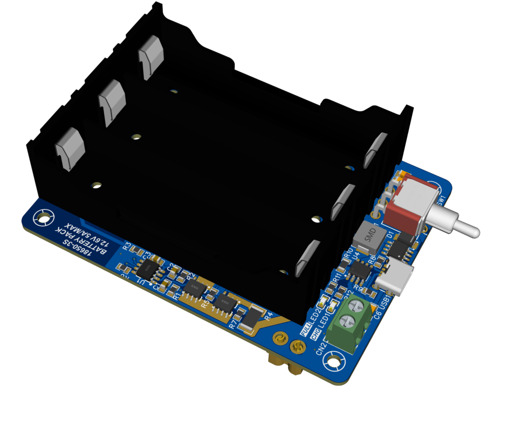
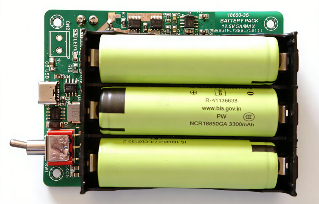
This compact 3S 18650 battery board PCB is designed for portability and reliability, with a layout optimized for its power-supply role. A three-cell battery holder is placed on top, while the other electronic components are arranged around it. The board is the same size as the rotator controller board. It is designed to stack above the controller board on four copper standoffs, and the two boards connect through a pair of XT30 connectors that deliver 12 V power down to the controller board. The red toggle switch on the right controls charge and discharge mode. Move the switch left to charge the battery when USB is connected. Move it right to deliver 12 V from the XT30 connector.
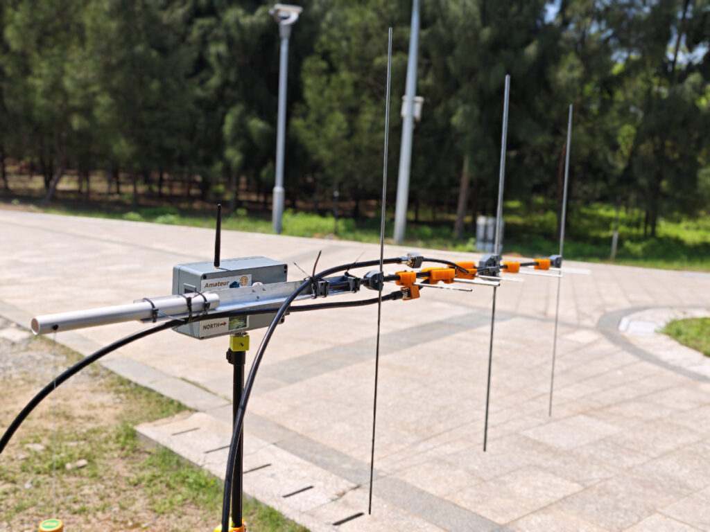
Finally Assembled Unit
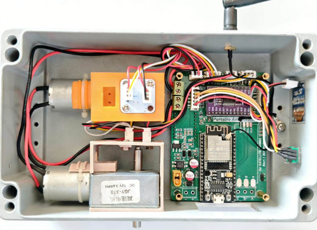
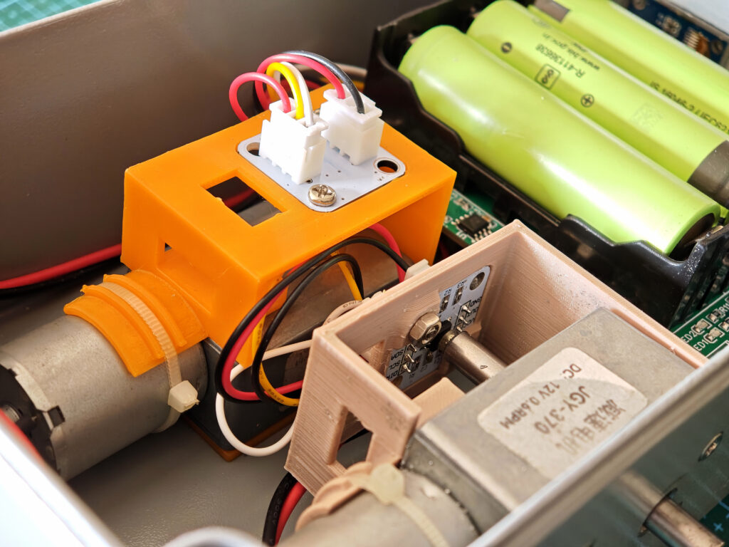
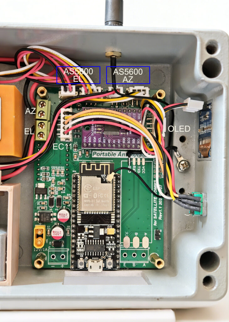
As you could see from the pictures above, two AS5600 encoders are mounted on 3D-printed brackets, which are secured to the motors with cable ties and screws. Eight countersunk M3 x 8 mm screws are used to secure the AZ and EL motors to the inner wall of the enclosure. I printed the motor CAD outline on paper, placed it where the motors should be installed, and taped it to the outer wall of the enclosure. This served as a drilling template for the motor holes. Other holes also needed to be drilled, including four holes for the board and two larger holes for the EC-11 encoder and Wi-Fi antenna.
The main controller board was secured to the right of the two motors with four M3 countersunk screws. Each motor system, AZ or EL, has power cables (MA, MB) for the motor, power cables (+3.3 V, GND) for the AS5600 sensor, and signal wires for DIR and I2C. The EC-11 encoder connects to the 5-pin XH2.54 socket on the left side, and the OLED connects to the 4-pin XH2.54 socket on the right side. An SMA-to-IPEX jumper cable extends the Wi-Fi antenna port outside the enclosure.
The battery board was placed on top of the controller board and powers it through the XT30 connectors.
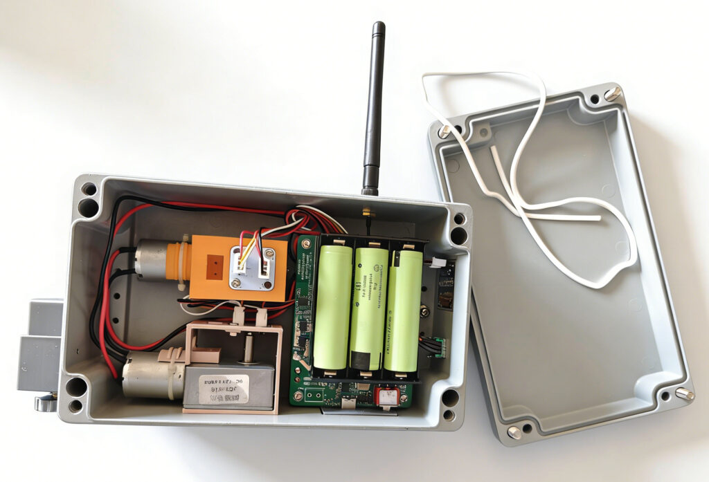
The fully assembled rotator weighs 1.6 kg including batteries, which is a bit heavy. The aluminum enclosure contributes most of its mass. I also built another version with a plastic enclosure, which is only about half the weight of the aluminum version. However, the plastic box should be shielded internally with flexible copper tape to avoid interference from the radio during transmission. Without shielding, RF interference can frequently reset the rotator.