Disclosure: This is a review of the open-source project from maker TheLight, named “A Music Visualizer Clock.” It’s a small DIY desktop gadget that combines a digital clock, music visualizer, and environment sensor. The ultra-low power feature is the highlight of the project. We’re now sharing this handy maker project with electronics hobbyists around the world.
Overview
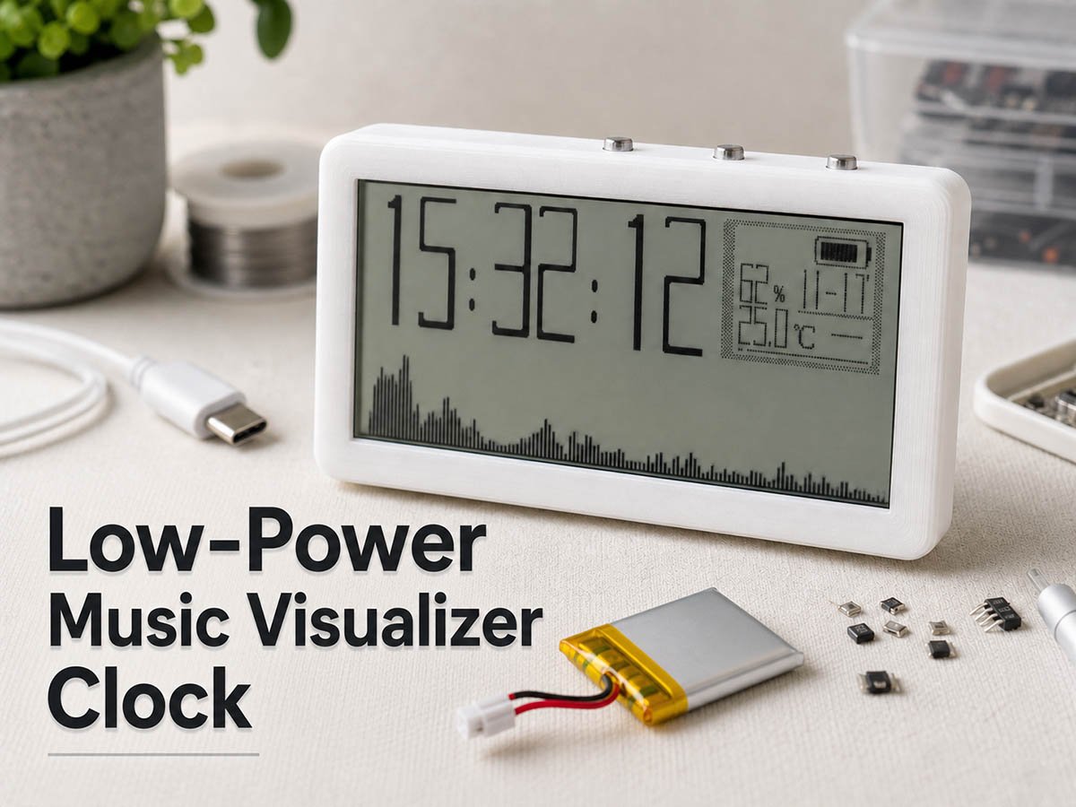
The music visualizer clock is an open-source DIY project from maker TheLight. The design runs on an N32L403 microcontroller and uses a 2.9-inch reflective black-and-white screen. This gadget has four display modes. It shows time and date, plus three different music visualizer animations. Every part used in this design is carefully tuned to save battery life.
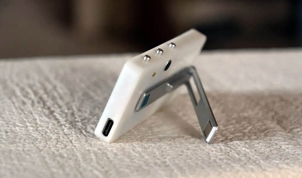
The project doesn’t include many parts and can be built with hand soldering in about an hour. It has a USB-C port for firmware updates. It’s a great pick for makers who want to learn the value of low-power design and build a useful desktop gadget.
In the following sections, we will break down the project, covering its value, key features, build cost and time, tips, and open-source files for those who want to replicate it.
Project Value & Skills Learned
This project stands out for its great low-power design. Low-power skills are critical for such a portable electronic gadget, and more importantly, this build isn’t just a demo—it’s a usable tool. Most projects in the maker community highlight lots of other features, with little or no coverage of power saving on a battery-powered device. The music visualizer clock lasts a long time on a single charge. By building it, you will know how to organize the microcontroller, power management units, sensors, and displays together, and make them run in an efficient way.
Skills you’ll gain:
- N32L403 programming and its low-power mode setup
- FFT audio processing by ARM DSP libraries
- SD3900 RTC interfacing and programming
- Interfacing an analog microphone to an MCU, including analog signal amplification and ADC sampling
- 0402 SMT soldering and PCB assembly
- Programming a monocolor reflective display (384*168)
- Lithium battery charging and power management
- Programming a SHT40 environmental sensor
Hardware Deep Dive: Engineering and Design
This project is centered around a low-power architecture, focusing on maximizing battery life while maintaining real-time audio visualization and sensing capabilities.
Block Diagram:
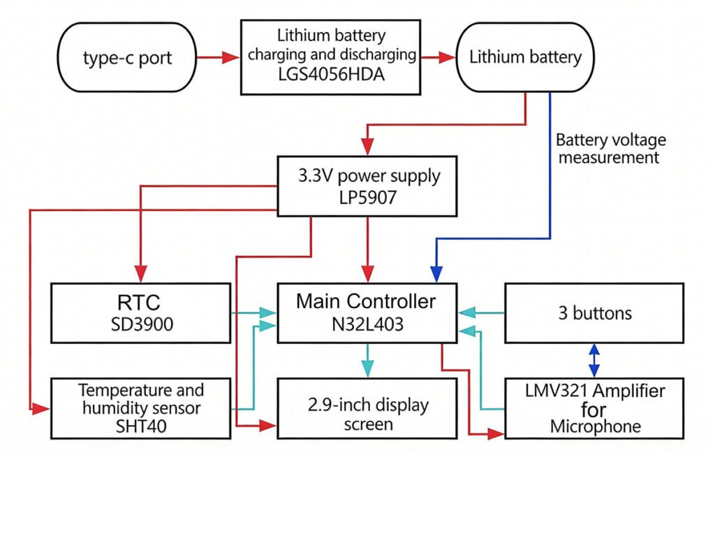
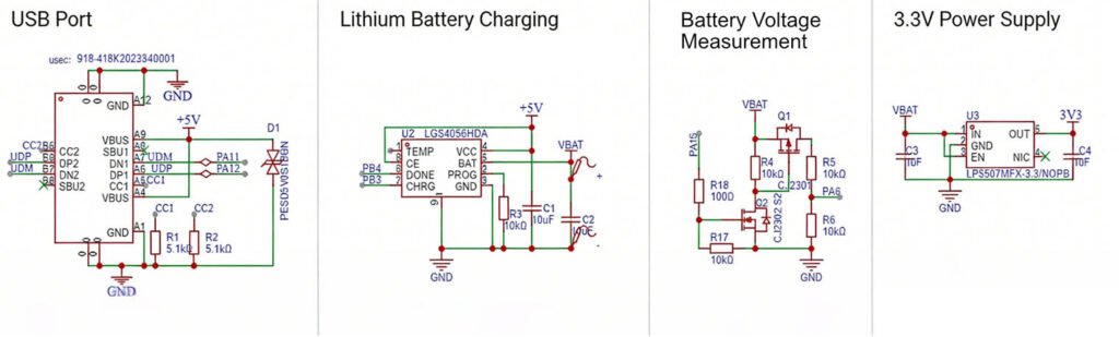
Power Supply:
The power system is optimized for high efficiency and minimal interference:
- Simplified Switching: To streamline the hardware, the design omits a dedicated power switching circuit between USB and battery power.
- Ultra-Low Current: The board’s operating current is less than 10mA, which is lower than the termination current of the LGS4056 charger.
- Low-Noise LDO: A LP5907 regulator is used for the 3.3V supply to minimize power supply noise, which is critical for the sensitivity of the microphone circuit.
- Battery Efficiency: The battery voltage measurement circuit uses an NMOS+PMOS control configuration to toggle the connection, significantly reducing static power consumption.
- Update (V1.4): The lithium battery charging IC has been upgraded from the LGS4056 to the SK4554D8-42.
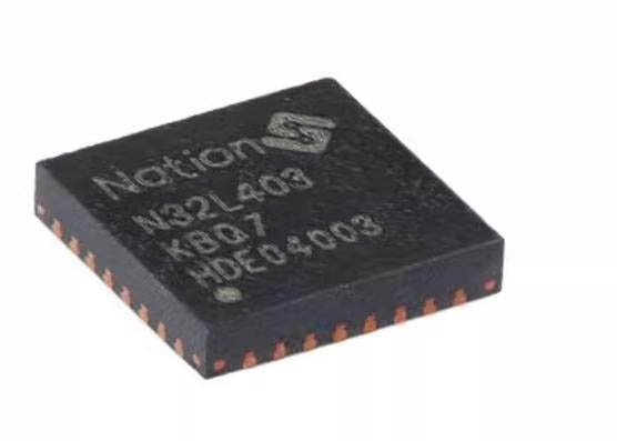
Microcontroller Selection:
As the primary power consumer, the MCU was chosen for its balance of performance and efficiency:
- Model: N32L403KBQ7 (M4F core, 64MHz, 128K Flash, 24K SRAM).
- Efficiency: At 64MHz (using the internal RC clock), the current draw is 3.7-5.9mA; in STOP2 mode, it consumes only a few microamps and can wake up in 12µs.
- Computational Power: The M4F core supports the ARM-DSP library, which accelerates FFT calculations for the music spectrum while further reducing power usage.
Microphone and Amplifier Design
- Microphone: A 6050-spec microphone with -26 ±2dB sensitivity was selected. High sensitivity is required for picking up sound from a longer distance.
- Operational Amplifier: An LMV321 is used in an inverting amplifier configuration due to its low power consumption and sufficient bandwidth for the 20KHz ADC sampling rate.
- DC Biasing: Since the MCU’s ADC cannot measure negative voltages, a 1.64V bias is provided to the audio signal during amplification.
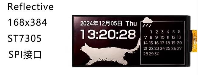
Display
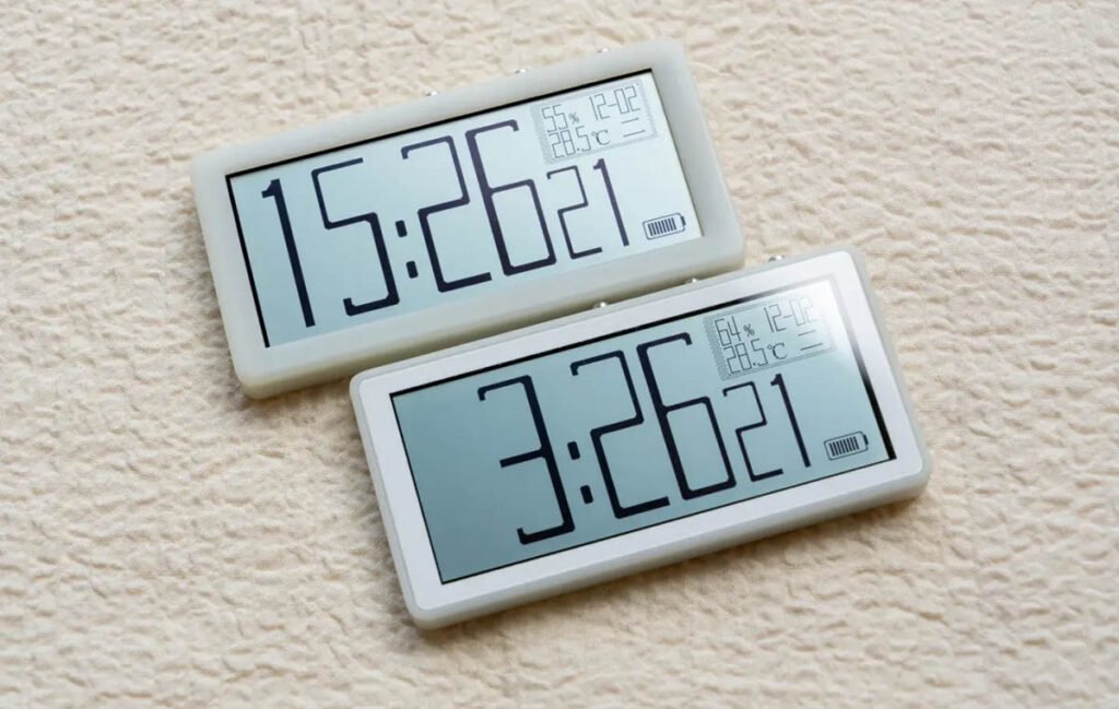
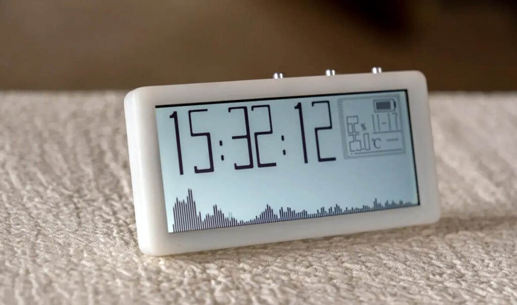
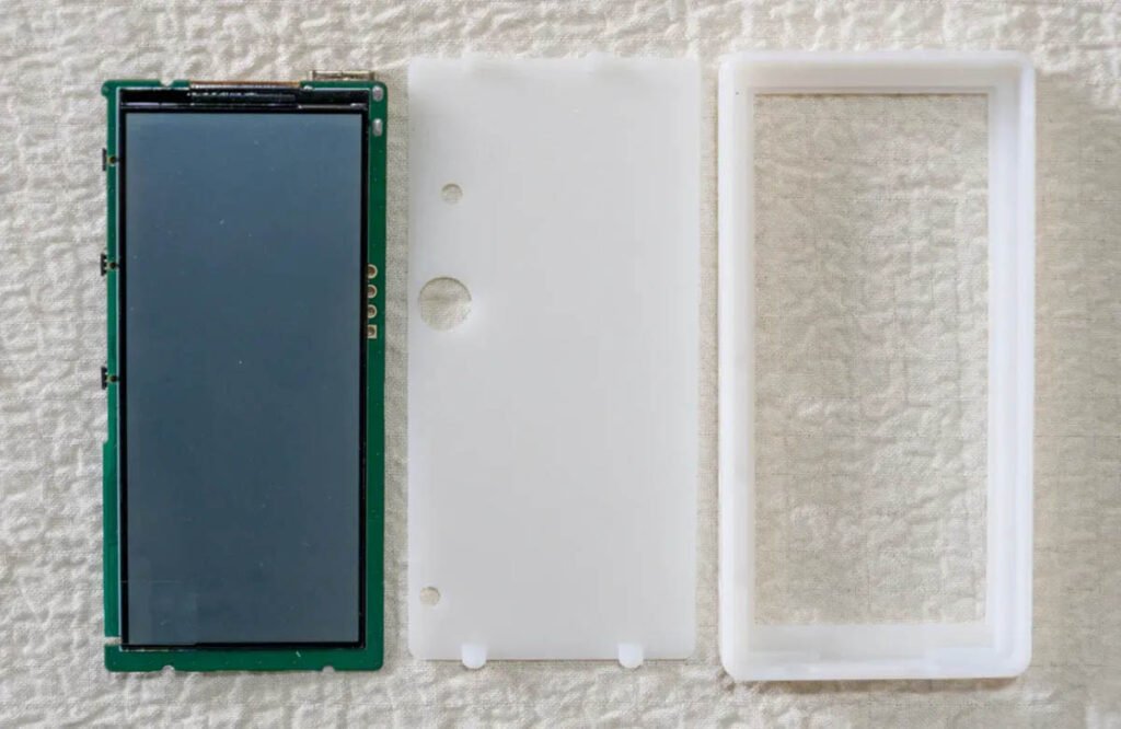
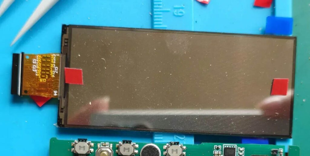
- LCD: A 2.9-inch Monochromatic Reflective Display (YDP290H001-V3, 384×168 resolution).
- Advantage: Unlike backlit screens, this reflective panel has no backlight, and it consumes significantly less power.
- Refresh Rates: The system switches between 1Hz (for time/date display) and 51Hz (for music spectrum). The static current required to maintain the display is approximately 19µA and 560µA, respectively.
RTC and Sensors
- RTC (Real-Time Clock): The SD3900 (3225 package) features an integrated crystal and temperature compensation. It operates at 0.8µA with high precision (±3.8ppm).
- Environmental Sensor: The SHT40 provides temperature (±0.2℃) and humidity (±1.5%RH) monitoring with an average current of only 0.4µA at a 1Hz measurement frequency.
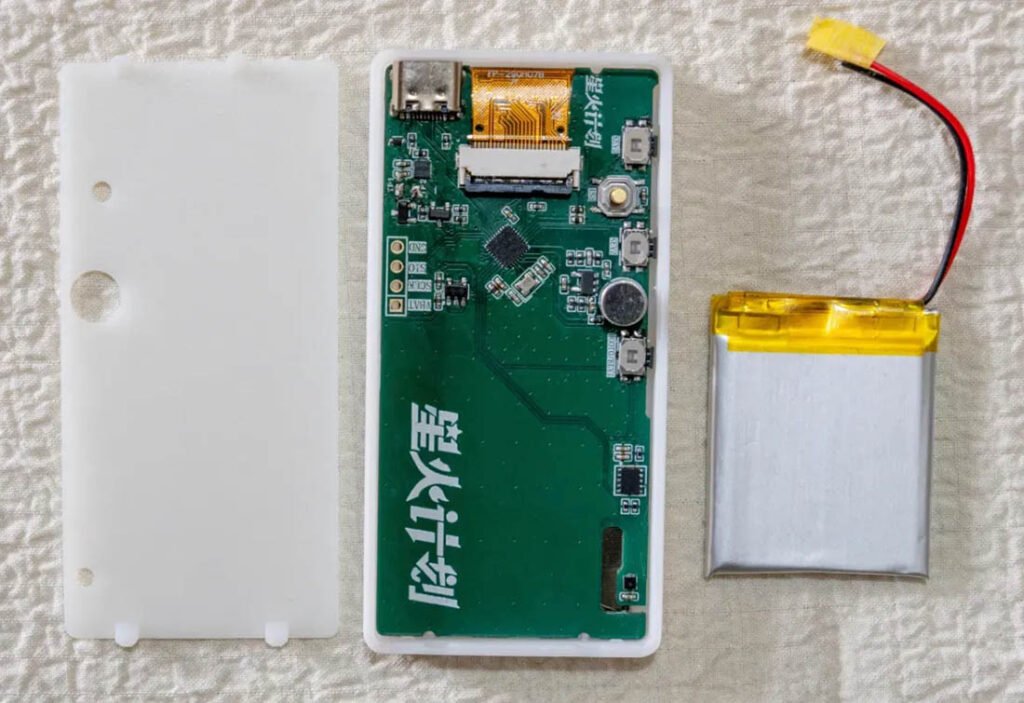
About Battery
The project uses a 303040 soft-pack lithium battery with an integrated protection board. The layout prioritizes ease of soldering over the most compact component density.
Software Implementation and Logic
The firmware is developed using the GCC compiler within the VSCode EIDE environment. It focuses on balancing high-performance audio processing with extreme power saving.
1. Audio Acquisition and FFT
- Sampling Strategy: The system uses the TIM3 timer’s TRGO function to trigger ADC sampling at a rate of 20KHz (10KHz effective bandwidth).
- DMA Transfer: To reduce CPU overhead, data is moved to memory via DMA. Once 256 samples are collected, a DMA interrupt triggers the processing routine.
- Signal Processing: Before doing the FFT calculation, the DC offset (bias voltage) is subtracted from the raw ADC data.
- FFT Library: The firmware leverages the ARM-DSP library for floating-point FFT calculations.
- Optimization: Data is processed using a Hamming window to reduce spectral leakage, followed by a logarithmic transformation to produce intuitive frequency spectrum bars.
2. Display and Rendering
- Controller Compatibility: The screen uses the ST7305 controller. Each byte in the display RAM maps to 4 vertical pixels across 2 adjacent columns, which takes a lot of the MCU’s computation ability.
- Rendering Logic: To maintain a high refresh rate (50Hz) without excessive power consumption, the system separates spectrum rendering from the clock’s time-changing animation.
- Graphics Acceleration:
- Spectrum: Directly manipulates CGRAM based on the spectrum’s line length.
- Time Animations: Font frames are pre-cached in RAM and copied to CGRAM frame-by-frame during animations.
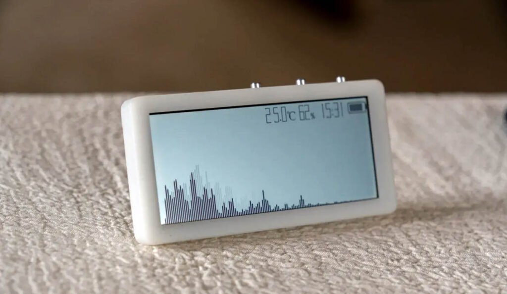
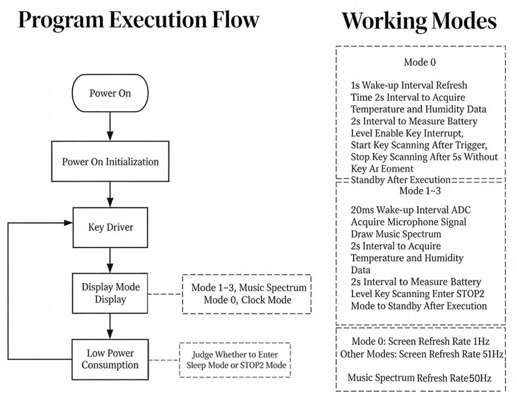
3. Power Control Modes
- Mode 0 (Time & Date): Wakes up every 1 second to update time, sensors, and battery status. The screen operates in a 1Hz low-power mode.
- Modes 1-3 (Spectrum): Wakes up every 20ms. While the ADC/DMA collects the next batch of audio data, the CPU simultaneously performs FFT and UI rendering.
- Sleep Optimization: After sending data to the screen via SPI DMA, the MCU enters sleep mode until all the peripherals complete their work, then it enters STOP2 mode for maximum efficiency.
- Resource Management: Peripherals like the ADC, timers, and microphone amp are fully powered off when working in Mode 0.
Cost & Build Time
This breakdown uses the creator’s official parts list and LCSC sourcing for a realistic build plan:
- Total Cost: ~$9 (±$2) – postage and the cost of the 3D-printed enclosure are not included
- Build Time: 4–6 hours – includes soldering, firmware uploading, assembly, and testing (time for 3D printing is extra)
- Difficulty: Upper-intermediate – you have to do 0402-sized SMT soldering
- Software Setup: Moderate – pre-built firmware is available for beginners; advanced users can edit the code
Note: The cost doesn’t cover shipping fees, 3D printing filament/resin, or the 0.5mm acrylic sheet. All main electronic parts are easy to order via LCSC except the LCD. You can order the LCD from AliExpress.
Key Hardware Parts
- MCU: N32L403KBQ7 (Cortex-M4F)
- LCD: 2.9” reflective display (YDP290H001-V3, 384×168, no backlight)
- RTC: SD3900 – high precision with tiny power draw
- Sensor: SHT40 – measures temperature and humidity
- Audio: 6050P analog microphone + LMV321 OP amp
- Power: SK4554D8-42 battery charger, LP5907 3.3V regulator
- Battery: 3.7V 450mAh lithium battery (built-in protective circuitry)
- Controls: 3 buttons, reset switch, USB-C (firmware upload/charging)
- Case: All 3D-printable, with optional acrylic panel sheet
Core Features
- Ultra-Low Power Consumption: 23uA in sleep; 142uA in clock mode (132-day battery life); 4.2mA in music visualizer mode (4-5 day battery life)
- Display Modes: 1 clock/date mode + 3 music visualizer modes
- Smooth Visuals: 50Hz spectrum refresh, mic sensitivity adjustable
- Power Savings: Low-power consumption, low screen refresh rate in clock/date mode
- Environmental Sensor: Temperature and humidity readings
- Battery Safe: Voltage monitoring, low-battery shut-off, USB-C charging
- Simple Controls: Short and long presses for mode and menu settings
- Easy Updates: USB-C firmware updates
- Full Open Source: Schematics, code, 3D files
Build Tips & Warnings
- PCB Design: The board was designed in EasyEDA and manufactured by JLCPCB. The PCB is 1mm in thickness instead of 1.6mm.
- Enclosure: Two versions of the 3D-printed case are available (one with an acrylic panel sheet and one without).
- Capacitors: C17~C22 must have a voltage rating of at least 25V.
- Where to start and stop: It is recommended to solder the N32L403 and charging IC first, saving the SHT40 and microphone for last.
- Soldering: Check all your soldering before powering it up.
- Microphone: Trim the pins short and pre-tin the negative terminal before mounting.
- Screen Installation: Upload the firmware before attaching the screen (sticking the display with double-sided adhesive tape). This avoids damaging the display if rework is needed.
- Firmware Upload: Uses the Nations MCU Download Tool via USB (DFU mode). If the device is not recognized by your computer, short 3V3EN to GND for one second to enter DFU mode. Please make sure you have the DFU drivers installed on your computer.
- SHT40: Make sure the SHT40 sensor window is clean with no solder flux sticking on it. Clean it carefully if needed.
- Acrylic Panel Sheet: Align the acrylic panel sheet carefully before sticking it on the enclosure.
Open-Source Files
All official files and tools are hosted on the creator’s verified pages. Everything is free and accessible.
- OSHWHub Project: https://oshwhub.com/thelight/low-power-music-spectrum-clock (schematics, BOM, 3D files, build notes)
- Code Repo: https://gitee.com/keleLight/N32L40X__2.9lcd_MusicSpectrum (editable source code)
- Firmware & Tools: Pre-built BIN file, DFU programmer, and drivers (on OSHWHub)
Final Thoughts
The Low-Power Music Visualizer Clock is a fantastic DIY project for any maker. It demonstrates how to implement low-power consumption design in an STM32-based microcontroller project. This isn’t just a demo. It’s a usable device that shows time, visualizes music, and tracks the environment. Moreover, the clock can run for months on a small battery, thanks to smart design.
Copyright Notice
This is an original review of the Low-Power Music Spectrum Clock by TheLight (project link: https://oshwhub.com/thelight/low-power-music-spectrum-clock). The original project uses a CC BY-NC 3.0 license. All images are credited to the creator TheLight.