
1. Introduction
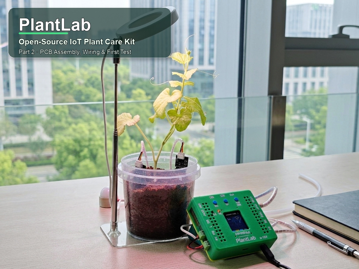
In Part 1, we centered on the hardware design of PlantLab, an open-source IoT plant care kit based on the ESP32-S3. We also introduced the sensors, actuators, schematic, PCB layout, and 3D-printed case.
In this part, we will focus on the real benchwork: solder the PlantLab PCB, install the ESP32-S3 development board and main modules, connect the sensors and 5V actuator outputs, place the board into the printed case, and run the first power-on test.
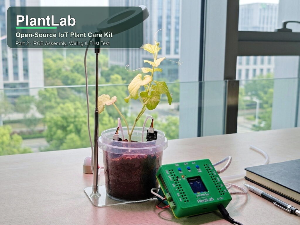
We also focus on some practical checks during the assembling: confirming the 12V input polarity, measuring the 5V and 3.3V rails, checking for shorts, aligning the modules properly, and testing the display, buttons, pumps, grow light, and sensor readings before using the system near water and plants.
By the end of this article, the PlantLab board should be assembled and ready for your real near plant deployment.
2. What You Need Before Assembly
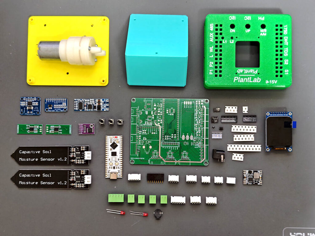
Before soldering, prepare the main parts and check them against the BOM file. The list below is only a quick overview. For exact values, package sizes, and quantities, always follow the BOM.
- PlantLab PCB
- ESP32-S3 development board
- MP1584EN DC-DC module
- ADS1115, INA219, and RS485 modules
- MOSFETs, transistors, resistors, capacitors, and diodes
- Pin headers, XH2.54 connectors, screw terminals, and DC power jack
- 1.69-inch TFT display, buttons, and buzzer
- Soil moisture sensors, DHT22, BH1750, and water level sensor
- Optional TDS, pH, DS18B20, and RS485 NPK sensors
- 5V pump, grow light, solenoid valve, or fan, depending on your setup
- 3D-printed case parts, screws, and wires
- Soldering iron, solder wire, tweezers, flush cutters, multimeter, and 12V power supply
Note: The RS485 NPK sensor is optional. For most low-cost multi-purpose agriculture sensors, soil moisture, temperature, and EC/salinity readings are the most useful. The pH, NPK, and “fertility” values are usually indirect estimates (not reliable), so use them only as rough references, not for precise fertilizing or pH adjustment.
3. PCB Assembly Overview
For PCB assembly, work from lower parts to taller parts. Start with the small SMD components, then solder the ICs and transistors, then followed by connectors, headers, plug-in modules, screw terminals, buttons, buzzer, and TFT display. This keeps the board flat on the desk and makes soldering easier, especially for a mixed SMD and through-hole build.
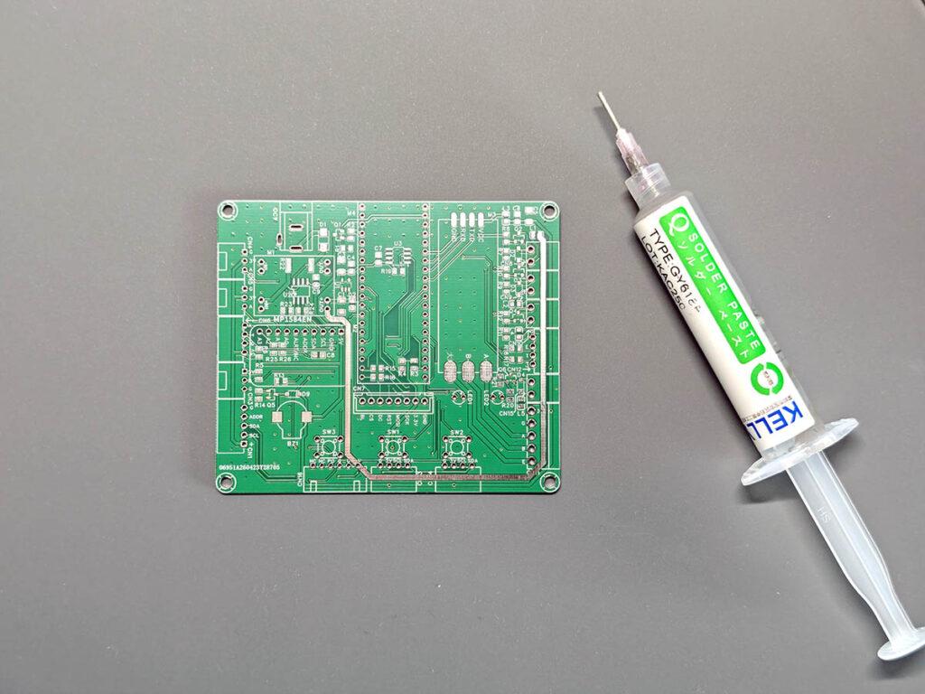
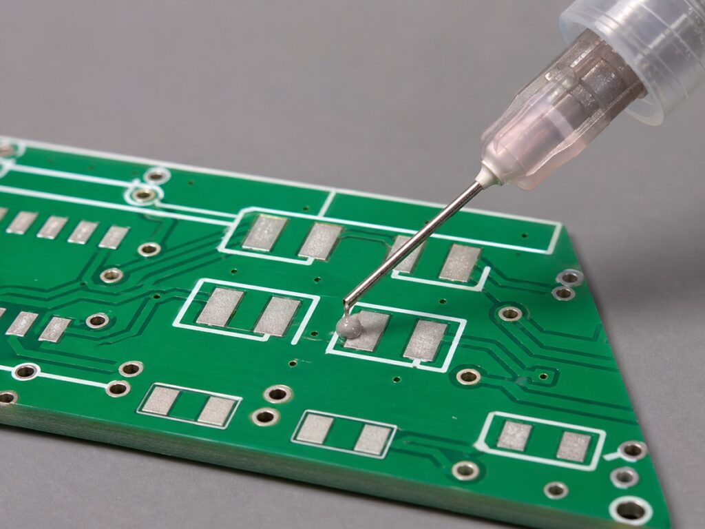
Apply solder paste to the SMD pads first. I used a solder paste syringe for this step. In theory, each pad only needs a tiny dot, but in real assembly it is not always easy to control, especially around small IC pins. Some paste may look messy before heating, and that is fine. During reflow, the melted solder pulls itself onto the pads. In my build, I placed the resistors, capacitors, diodes, transistors, and ICs with tweezers, then heated the PCB on my homemade reflow hot plate. After the board cooled down, I inspected the joints and fixed any bridges with a soldering iron. This is a basic but very useful skill for hardware makers.
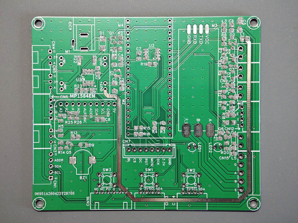
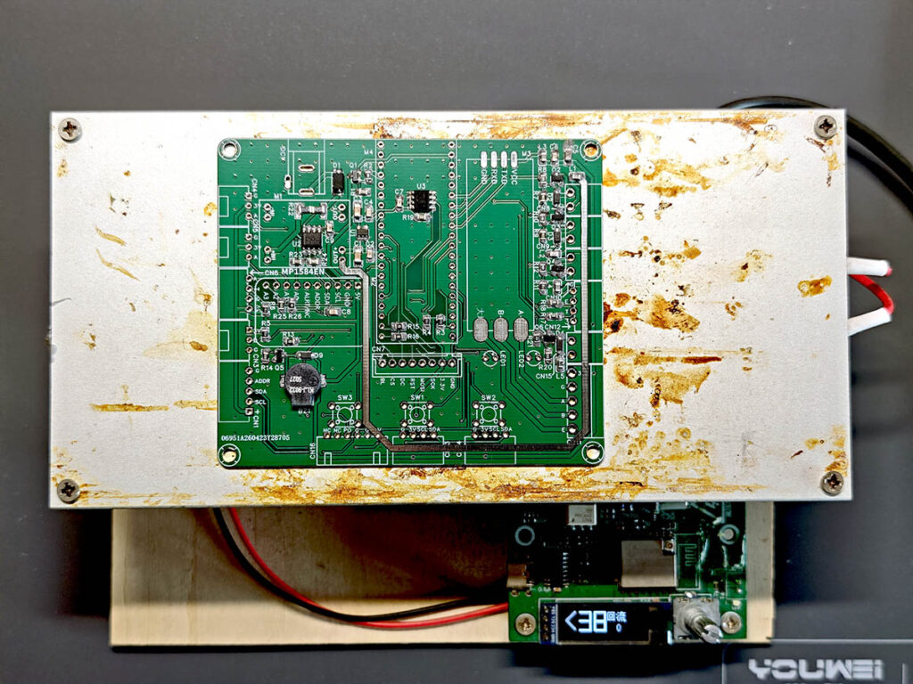
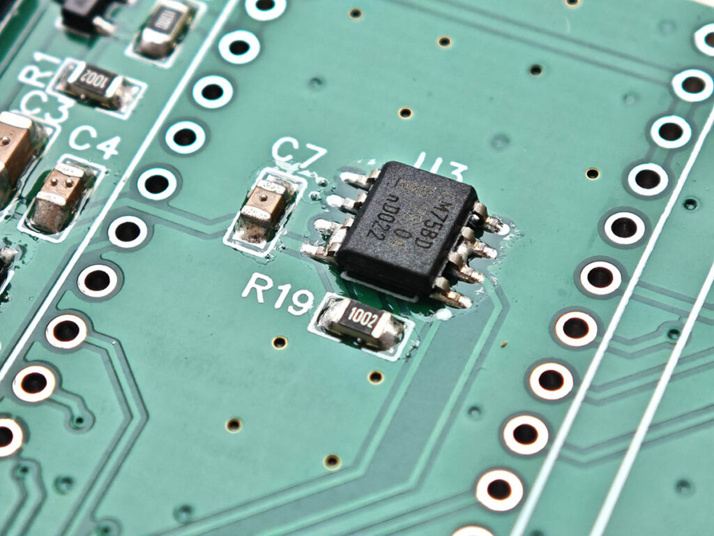
After reflow and touch-up, inspect the SMD solder joints under good light. Check for solder bridges, shifted parts, and weak joints. In the photo above, you can see a few bridges around U3; I fixed them later by hand soldering, as shown in the photo below. On my board, the small resistors, capacitors, diodes, transistors, ICs, buzzer, and indicator LEDs were all soldered in place after this cleanup. This is also a good point to compare the board with the PCB silkscreen and schematic before moving on to the taller through-hole parts and plug-in modules.
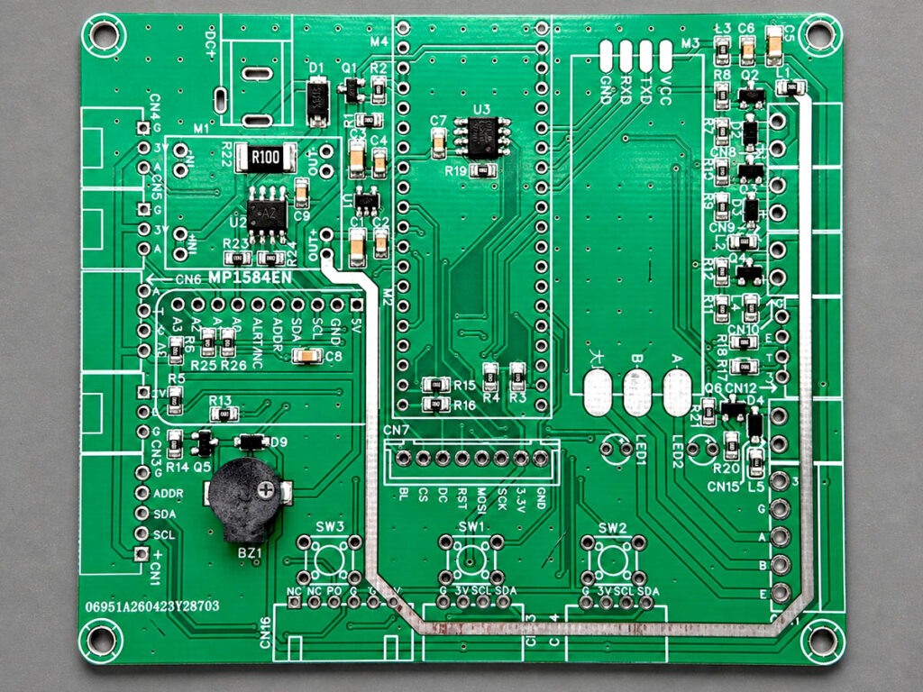
Tip: Keep the syringe needle close to the PCB, press gently, then lift straight up. Do not worry too much if a few pads get extra paste. Clean the obvious excess before heating, and fix any solder bridges later with a soldering iron.
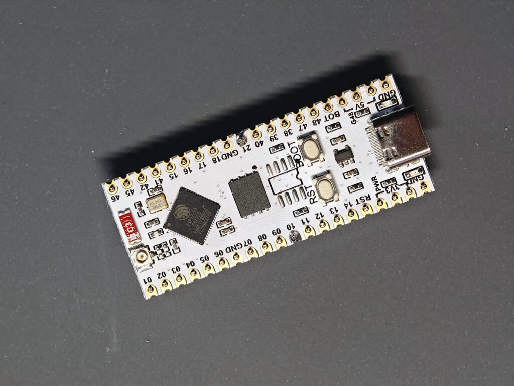
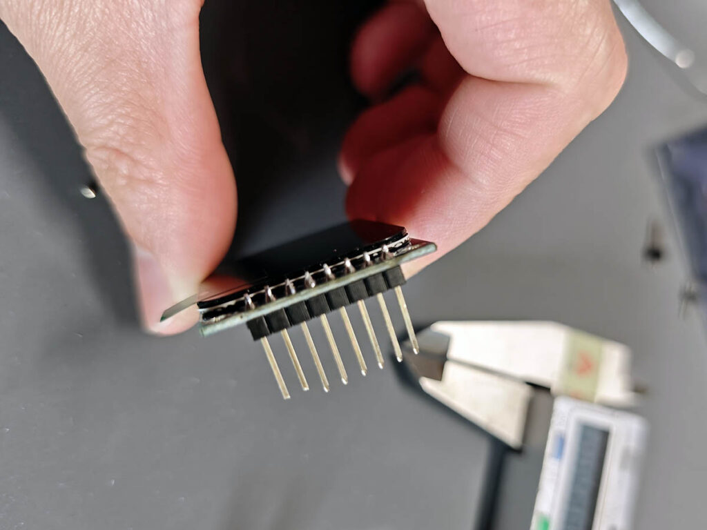
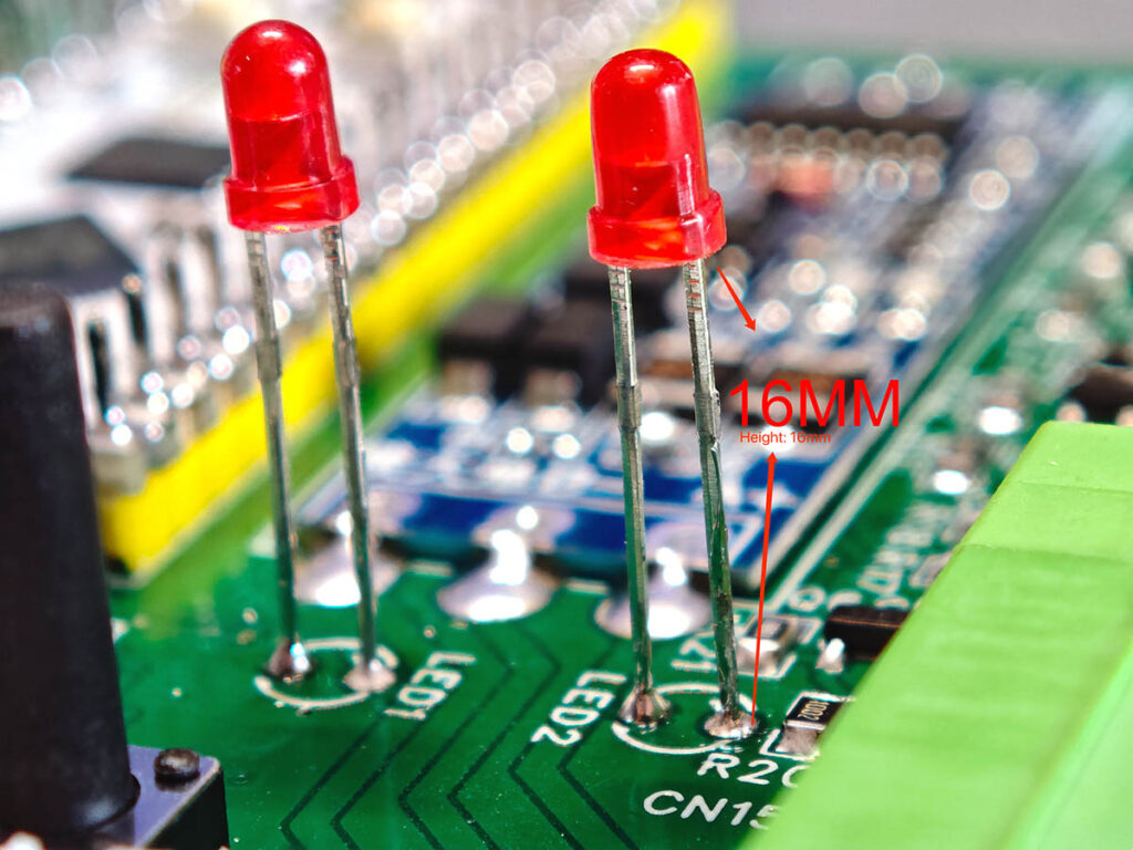
After the SMD parts are finished, move on to the through-hole parts and plug-in modules. Start with the pin headers for the ESP32-S3, ADS1115, RS485 module, TFT display, and other small modules. Before soldering them to the main PCB, check the header direction and pin length. For the TFT display, use long male pin headers, about 15mm, instead of the regular 11.3mm headers. The extra height gives the display enough clearance above the main PCB and helps it fit better with the front panel. A slightly tilted header can make the module difficult to install later, so keep the pins straight while soldering.
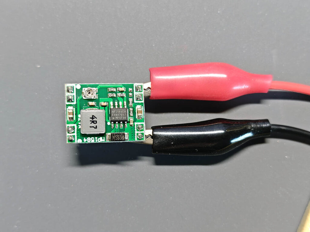
Test the MP1584EN DC-DC module separately before installing it on the board. Connect input power with alligator clips and adjust the output to 5V first. This step is important because many MP1584 modules have an adjustable output, and the PlantLab board should not be powered with the wrong voltage. Some MP1584EN modules have a fixed 5V output, but it is still good practice to test the voltage before installation.
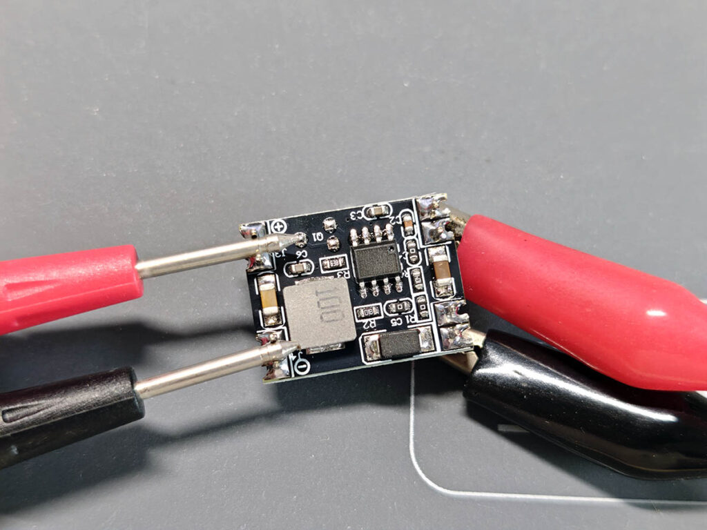
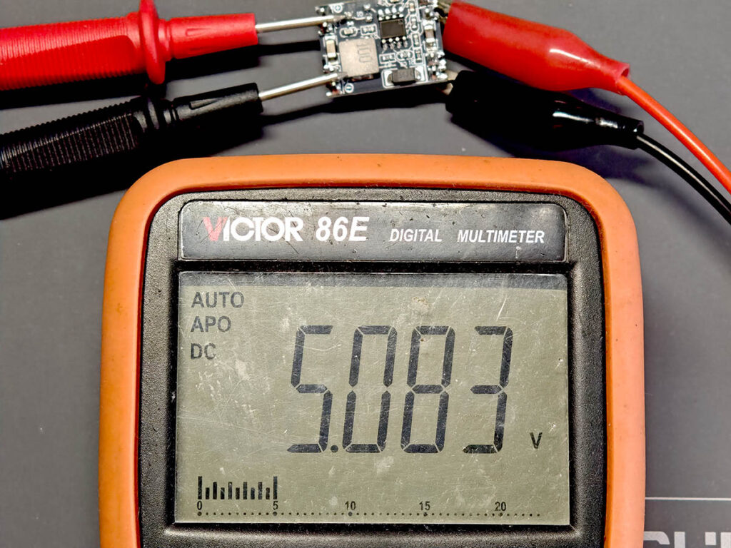
Then solder the modules onto the main PCB one by one. Install the ESP32-S3 development board with the USB-C port facing outward, so it can still be reached after the board is mounted in the case. Solder the ADS1115 module, RS485 module, MP1584EN module, and TFT display in their marked positions. After that, add the XH2.54 sensor connectors, screw terminals for the 5V actuator outputs, physical buttons, and the external antenna connector.
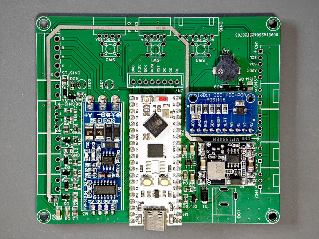
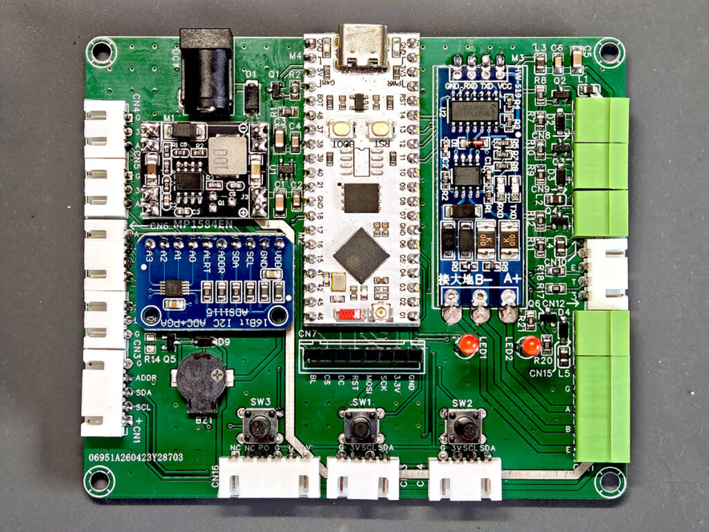
Now, the PCB already looks like a real controller instead of a bare board. Before moving to the power test, check the orientation of each module again, especially the ESP32-S3, TFT display, MP1584EN, and RS485 module. A quick visual check here can save a lot of debugging time later.
4. Power It Up
Before connecting other peripherals, test the power section first. Use a multimeter to check for shorts between power and GND on the 12V input, 5V rail, and 3.3V rail. If any rail looks shorted, stop and inspect the soldering before applying power.
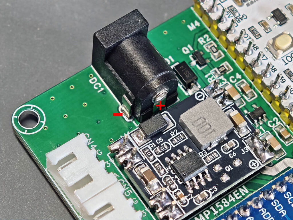
Start by checking the DC input jack polarity before plugging in the adapter. The center pin is positive, and the outer barrel is negative.
Next, test the USB power on the ESP32-S3. The power LED on the development board should turn on, and nothing on the PCB should get hot. This is a simple first power-up check before using the external 12V input.
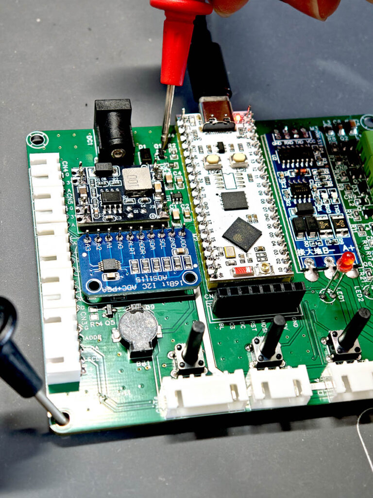
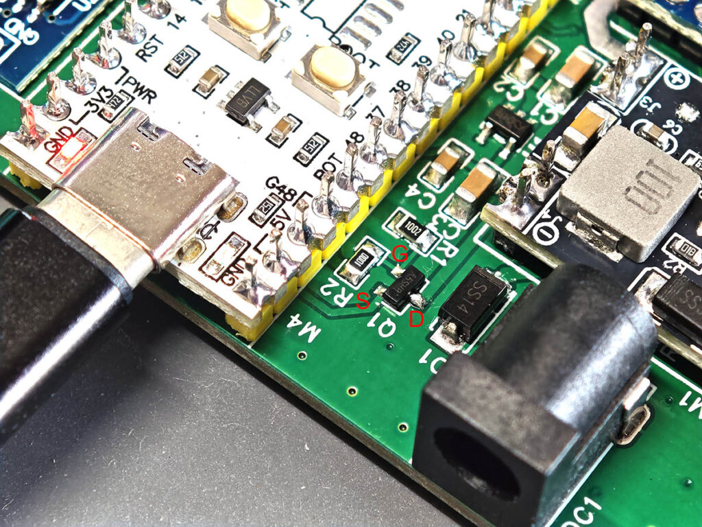
Then check the small power-switching area around Q1. With USB inserted, the source of Q1 should be 3.3V, and the gate should be 5.0V. In this mode, USB powers the ESP32-S3 development board only; it does not feed the main PCB 3.3V rail. In the close-up photo below, I marked the MOSFET pins as G, S, and D. This part controls the 3.3V power path between the development board and the main PCB. Make sure there are no solder bridges around Q1, R1/R2, and the nearby diode.
After these checks, connect the 12V input and measure the MP1584EN output again on the board. It should be 5V. Then check the LDO (U1) output; it should be 3.3V. Do this before connecting external sensors or 5V loads.
5. Uploading Firmware and Cables for Sensors & Actuators
After confirming the power rails are fine, the next is to flash the firmware before connecting all sensors and actuators. This is a PlatformIO project, but for the first setup I recommend using the fully merged release binary. It already includes the bootloader, partition table, firmware, and filesystem image, so beginners do not need to enter several flash addresses manually.
Keep the board powered from USB for flashing. If the ESP32-S3 is not detected, hold the BOOT button, tap RST, then release BOOT to enter download mode.
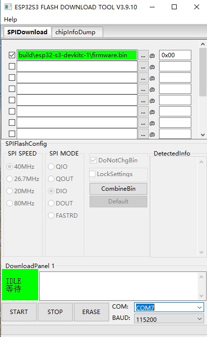
On Windows, use Espressif Flash Download Tool. Select the ESP32-S3 target, choose the correct COM port, load the merged binary, and set the flash address to 0x0. Then click START to write the firmware.
On macOS or Linux, flash the same merged binary with esptool. The serial port usually looks like /dev/cu.usbmodemxxxx, /dev/cu.usbserial-xxxx, or /dev/ttyUSB0.
python3 -m pip install esptool
python3 -m esptool --chip esp32s3 --port /dev/cu.usbmodemXXXX erase_flash
python3 -m esptool --chip esp32s3 --port /dev/cu.usbmodemXXXX --baud 460800 write_flash -z 0x0 plantlab-full.bin
If you want to modify the code later, use PlatformIO to build and upload from source:
pio run
pio run -t upload
pio run -t uploadfs
Before connecting everything at once, test the board step by step. Power up the board with a 12V power supply, then start with the TFT display and buttons. The display should turn on, and the buttons should respond in the menu setup. This confirms that the ESP32-S3, SPI display connection, and basic firmware are working.
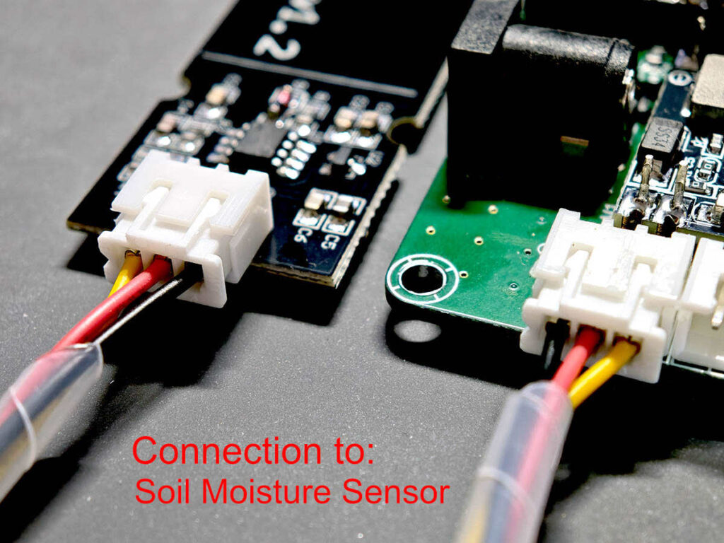
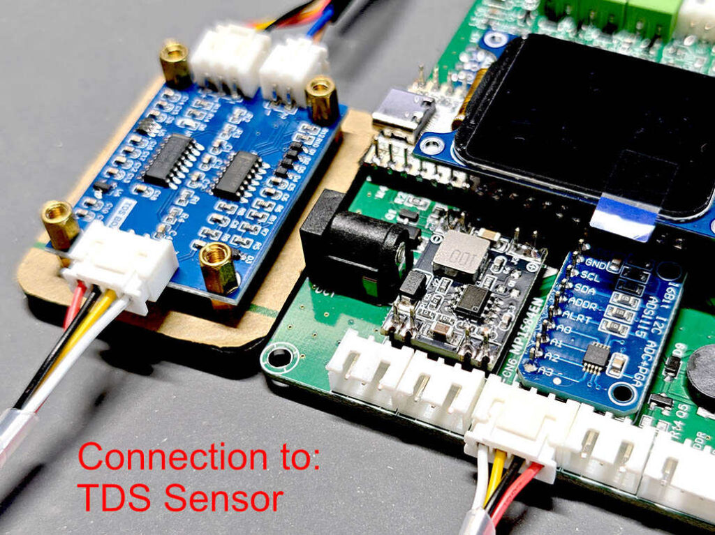
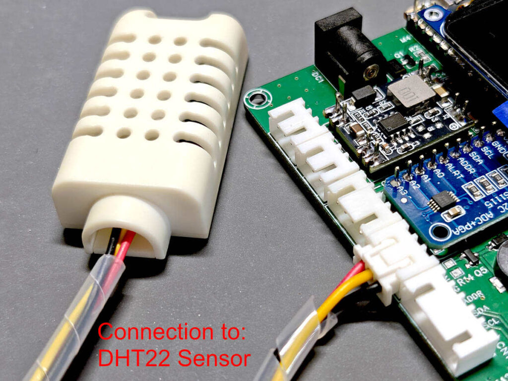
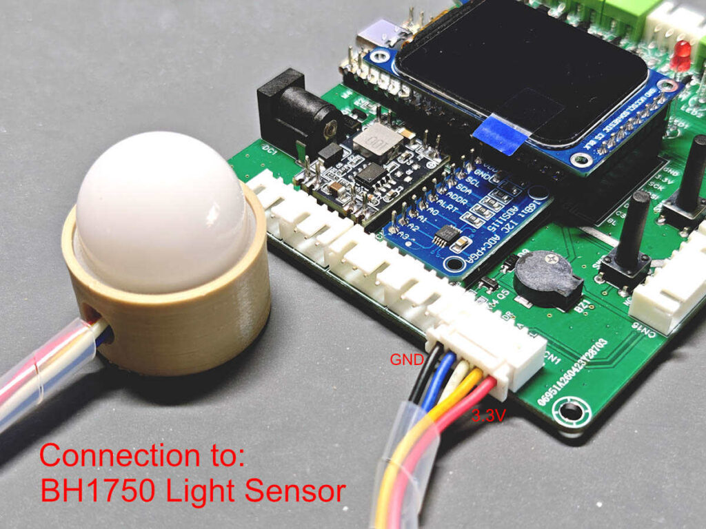
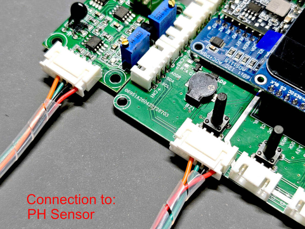
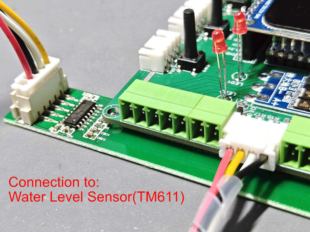
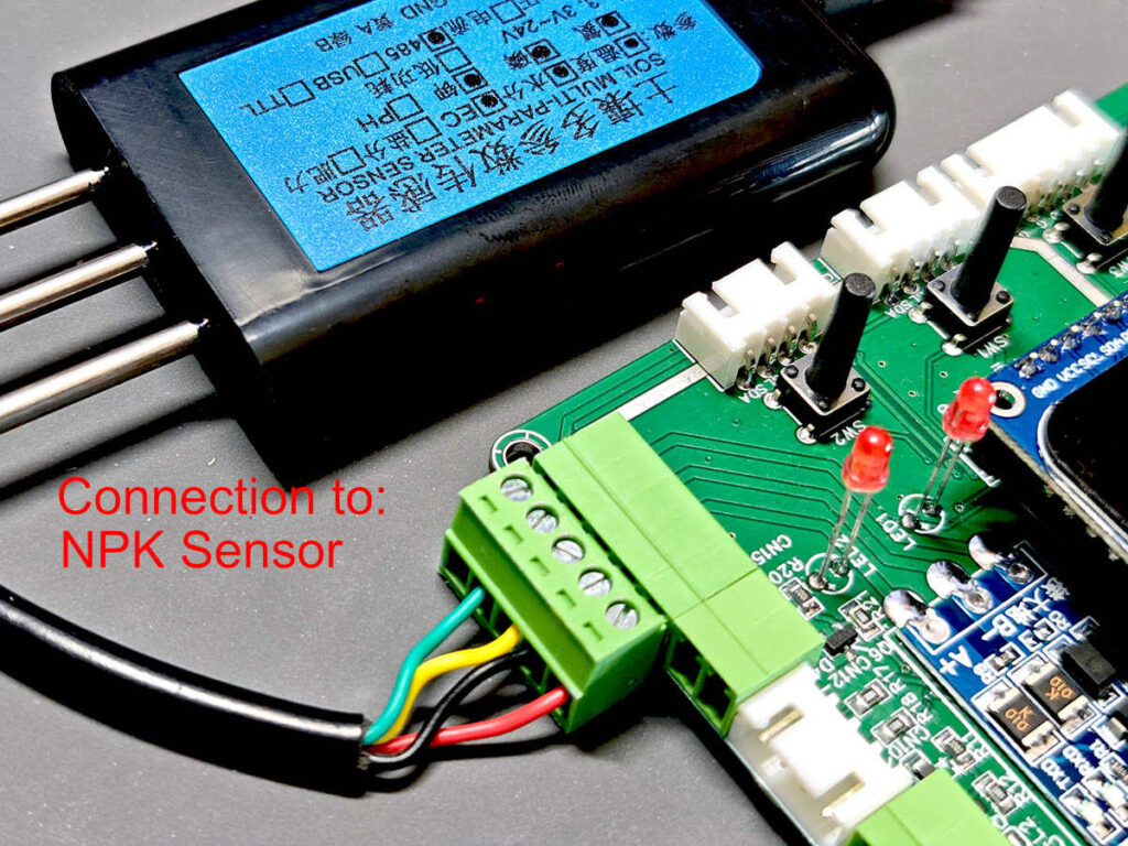
The board connects to the sensor modules through XH2.54 cables. In my build, the cables were about 50cm long. Different sensors use different pin counts, so prepare 3-pin, 4-pin, 5-pin, and 6-pin XH2.54 cables as needed.
Before plugging them in, check the pin count and pin order on both ends of each cable. Do not assume every ready-made cable has the same wire order. You may need to rearrange the pins on one end, or even both ends. A reversed VCC/GND cable can damage a sensor or the controller.
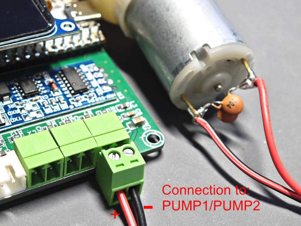
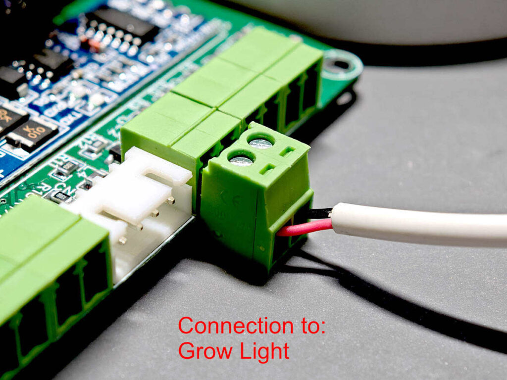
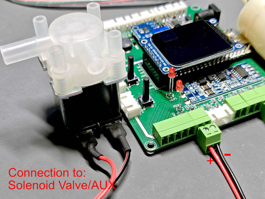
The photos below show the cable ends I checked before plugging them into the controller and sensor modules.
Notes:
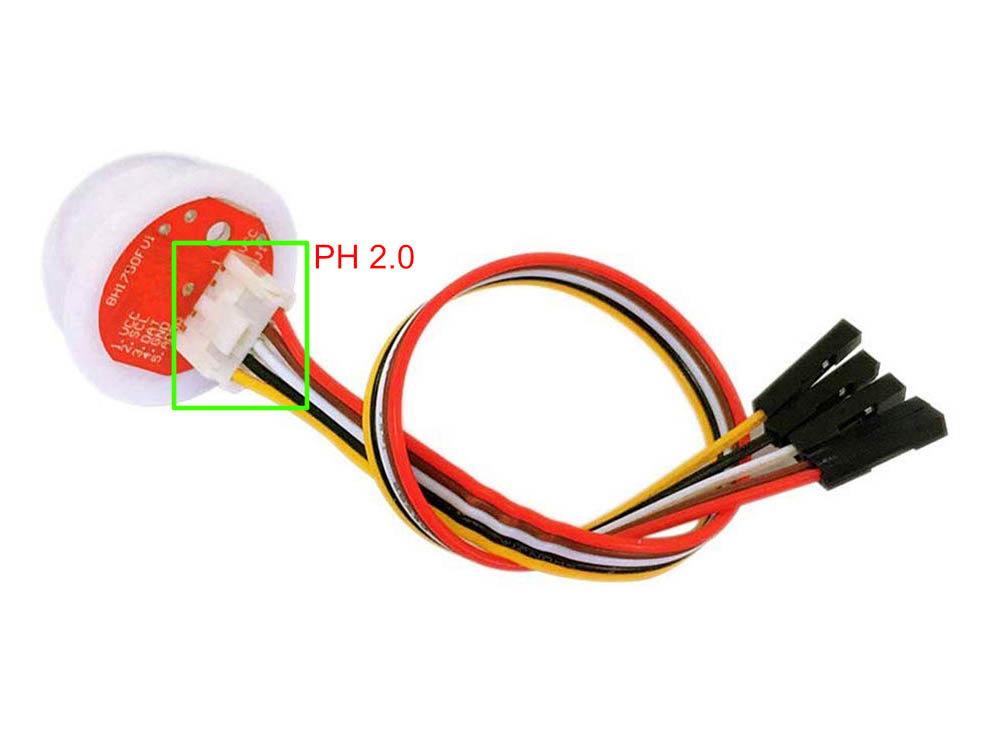
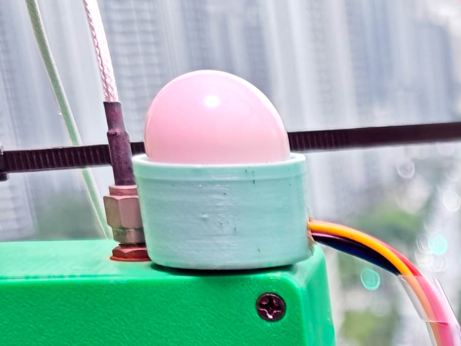
- For the BH1750 sensor, the cable is a little different: it uses a 5-pin XH2.54 connector on one end and a 5-pin PH2.0 connector on the other end. You may need to make this cable yourself by cutting the supplied PH2.0 cable and soldering the module to an XH2.54 cable. There is also a 3D-printed holder for the BH1750. Pass the cable through the holder first, before soldering or crimping the final connector.
- For the TDS sensor, the sensor module board has a 3-pin XH2.54 socket for the DS18B20 water temperature sensor. The TDS module connects to the main controller board with a 4-pin XH2.54 cable.
- For water level sensing, I use TM611 continuous water level sensor in the soil setup, and one D2LS-A 4-point sensor in the hydroponic setup. For both options, you need to make the cables yourself.
About sensor testing, start with the simple onboard sensors, such as the INA219 power sensor and LM75A temperature sensor. Then add the BH1750 light sensor, DHT sensor, water level sensor, soil moisture sensors, and finally the optional TDS or pH sensor. Remember to enable each sensor in the setup menu; otherwise, the firmware will not show its reading. The final TFT page lists the enabled sensors and their readings, which makes debugging much easier.
For the RS485 multi-purpose NPK sensor, connect A/B and power carefully, then check whether the firmware can read data from it. This sensor is optional, and its NPK/fertility values should only be used as rough references.
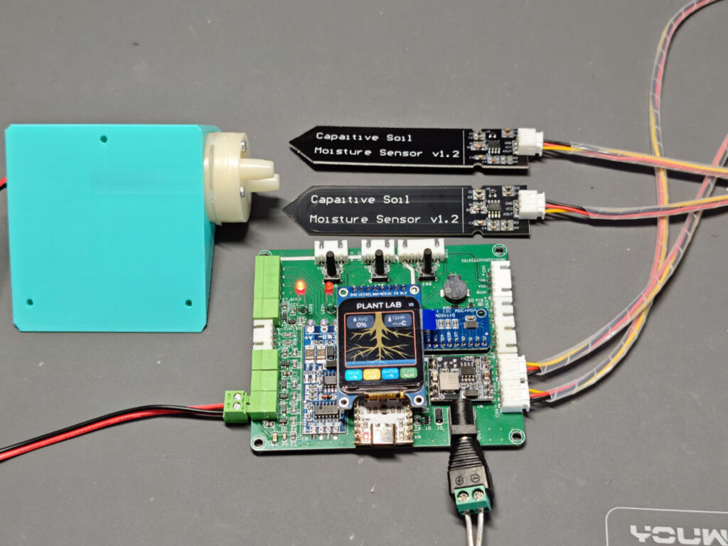
Wiring for actuators is simpler. Use regular black and white DC cables for the 5V pump, grow light, solenoid valve, or fan, then connect them to the screw terminals. Test each output manually in the firmware before connecting water tubes or placing the pump in water. It is much easier to fix wiring on a dry desk than beside a water tank.
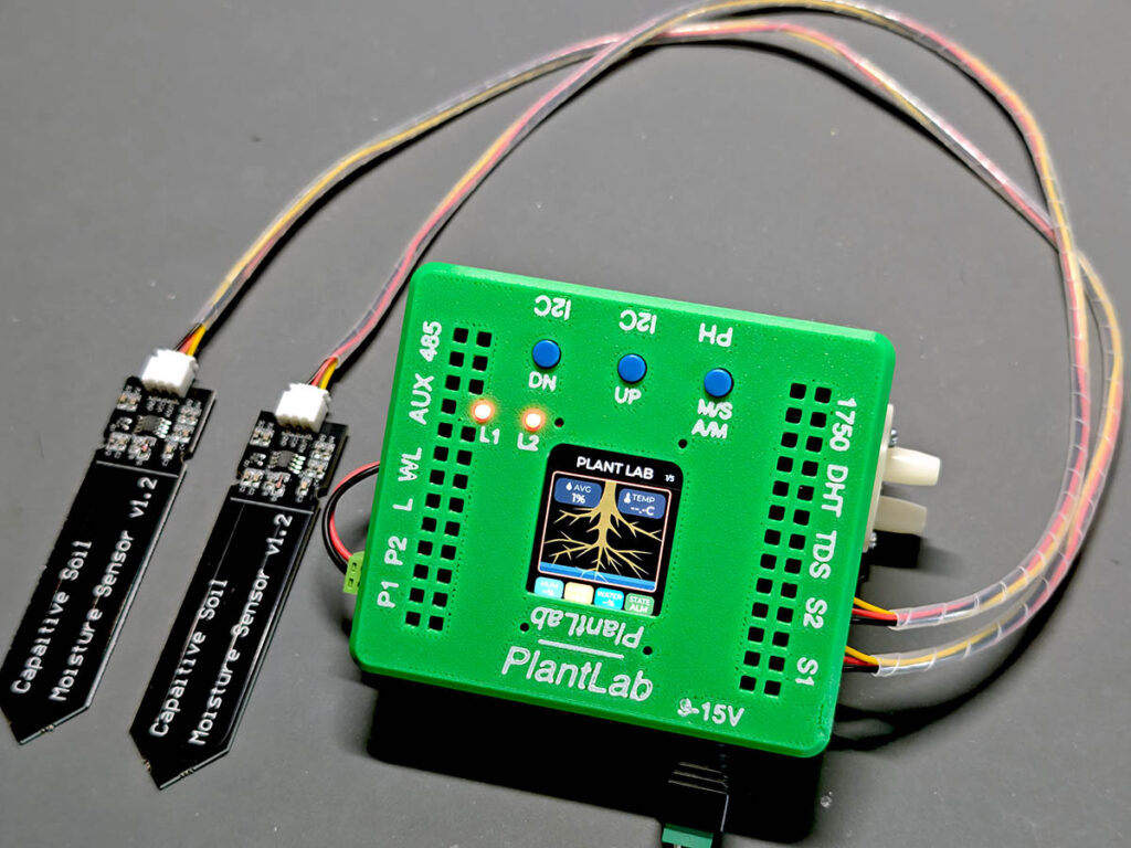
Keep the first test simple: one sensor, one pump, and one light output are enough to confirm the basic system. Next, you can add the remaining sensors and actuators according to your own plant setup. Please note that you do not have to install all sensors specified in this article. For a basic soil setup, two soil moisture sensors with one pump are a good start.
6. Installing the PCB Into the 3D-Printed Case
After the board passes the basic power and firmware checks, install it into the 3D-printed case. Do this before the final wiring, because the case openings decide how the sensor cables, actuator wires, display, buttons, and power jack are accessed.
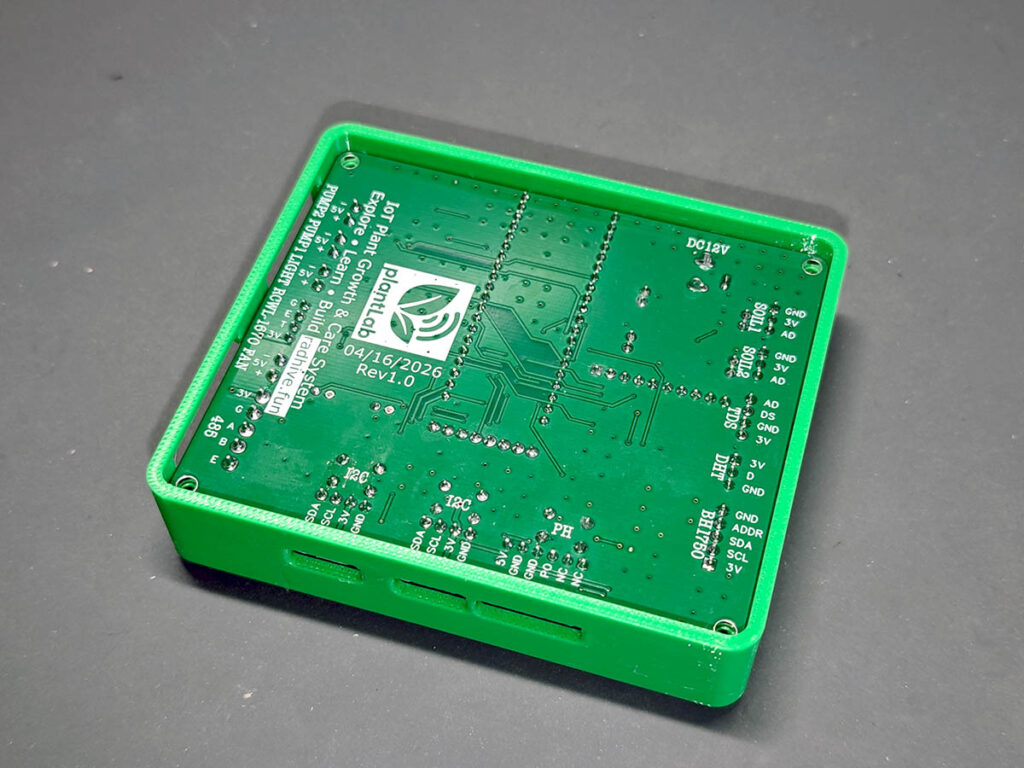
Place the PCB into the lower shell first. Keep the sensor connectors facing the opening side, and make sure the DC input, USB port, screw terminals, and XH2.54 ports line up with the cutouts. Do not force the board into the case. If one side does not sit flat, check whether a connector, solder joint, or printed edge is touching the shell.
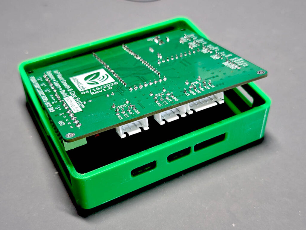
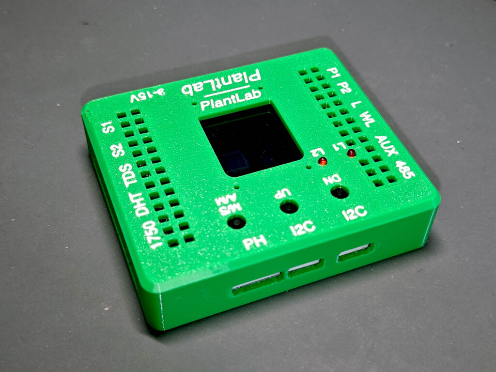
Before installing the top cover, check the display, LEDs, and buttons. The TFT should sit in the front window, the LEDs should be visible through their holes, and the three buttons should move freely. In my build, this was why I used the longer TFT pin headers, because it makes the display height match the front panel better.
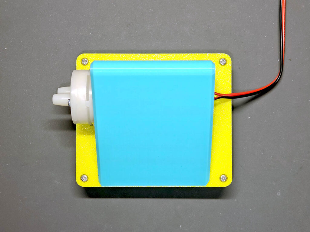
The printed parts also includes a rear stand with the opening for installing the pump. You should mount the pump into the stand. Keep the pump wires accessible so they can be connected to the screw terminal later.
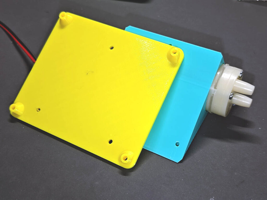
Use three M3 x 8 self-tapping screws to hold the rear shell (yellow) onto the stand (light green). Then use four M3 x 12 self-tapping screws to secure the front and rear parts of the enclosure together. Tighten them enough to hold the parts firmly, but do not overtighten them. Printed posts can crack if too much force is used, especially with small screws.
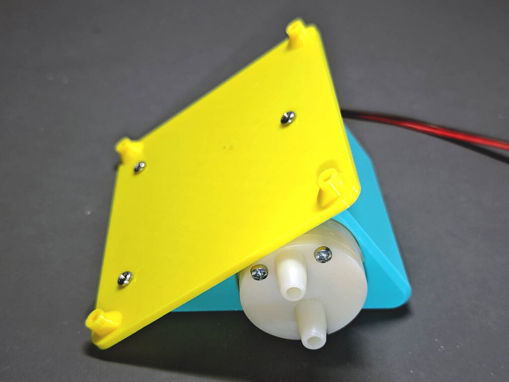
After assembly, the blue pump holder works as a rear support for the controller. This keeps the case tilted slightly and gives the water tubes a cleaner path away from the electronics.
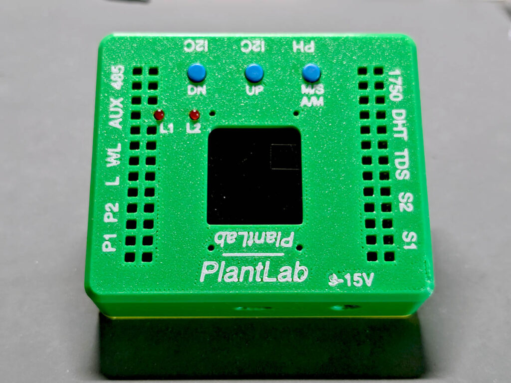
Finally, install the three blue button caps onto the buttons and check the front panel again. Now the display window, buttons, LEDs, ventilation holes, and printed labels are clear. Next, we’ll do a first power-on test.
7. First Power-On Test
Do the first full test on a dry desk. Do not put the pump tube in water yet, and do not connect all sensors at once. The goal of this step is to confirm that the controller, firmware, display, buttons, sensor ports, and actuator outputs are alive.
Start with the 12V adapter. After plugging it in, check that the board powers up normally and that the TFT display shows the main screen.
Next, press the three front buttons and check whether the TFT responds. Pressing DN or UP will cycle through the multiple TFT pages, where the sensor readings and actuator states are shown. The INA219 power reading and LM75A board temperature reading are good first indicators because they are built on the board. If these values appear on the TFT sensor page, we can confirm that the basic I2C bus and firmware are already working.
After that, add external sensors one by one. Plug in one sensor, enable it in the setup menu, and check the reading before moving to the next sensor. I tested the BH1750, DHT, water level sensor, soil moisture sensors, and optional TDS sensor in this way.
Test the actuator outputs last. Connect the 5V pump or a grow light to the output ports at a time, then trigger it manually from the firmware by pressing MS or A/M briefly. Use DN or UP to switch between different actuators. For the pump, keep it out of water during the first electrical test. You only need to hear or feel it run for a short moment.
For a basic soil setup, keep the first real test simple: two soil moisture sensors and one watering pump are enough. Once this works reliably, add the light sensor, grow light, water level sensor, and other optional parts.
8. Common Issues and Fixes
1. The ESP32-S3 is not detected by the computer
Use a real USB data cable, not a charge-only cable. If the port still does not appear, hold BOOT, tap RST, then release BOOT. On Windows, also check whether the USB serial driver is installed.
2. The firmware flashes, but the screen stays blank
First, confirm whether the system is actually running. Try to open the controller’s web page if you know the IP address. If one of the LEDs is flickering, the firmware is probably running and the problem is likely around the display. Next, check the TFT header. Make sure they are not poorly connected. Also make sure the merged binary was flashed, because the filesystem image is needed by the UI.
3. The board powers from USB, but the main PCB has no 3.3V
This is normal in USB-only mode. In this design, USB powers the ESP32-S3 development board only, but it should not feed the main PCB 3.3V rail through Q1. Use the external 12V input for the full board test.
4. The 5V rail is missing or wrong
Check the MP1584EN module. Some modules are adjustable, and some are fixed 5V versions. Measure the module output on the PCB. It should be 5V before any 5V pump, light, fan, or solenoid is connected.
5. A sensor shows no reading
First check whether the sensor is enabled in the setup menu. Then check the XH2.54 cable at both ends. Ready-made cables do not always keep the same pin order, and a reversed VCC/GND cable can make the sensor fail. For I2C sensors, also check SDA, SCL, 3.3V, and GND against the PCB label.
6. The BH1750 does not work
Check the custom cable. The BH1750 side uses a 5-pin PH2.0 connector, while the controller side uses XH2.54. You have to make this cable yourself by soldering one end directly to the sensor, so check those joints first. Also make sure the cable was passed through the 3D-printed holder before the final soldering or crimping; otherwise, you may have to remake it.
7. The RS485 NPK sensor does not return data
Swap A and B first. This is the most common RS485 mistake. Then check the sensor power. Even when it works, remember that the NPK and fertility readings from low-cost multi-purpose sensors are very rough references. Most of the time, these readings are not reliable enough for real fertilizing decisions.
8. The pump does not run
Check the screw terminal wiring and confirm the pump is a 5V load. Test the output manually in firmware by pressing MS or A/M, with the pump still on the desk. If the pump works from a direct 5V supply but not from the board, check the MOSFET output and the terminal connection.
9. The pump runs, but no water moves
Carefully debug this with the board in bare beside water. First check the tube direction and whether the pump is primed. Small 5V pumps sometimes need the tube shortened or the water tank placed closer before water starts moving smoothly.
10. The buttons feel stuck after installing the case
Loosen the case screws slightly and check the button caps. The caps should sit on the buttons without pressing them all the time. If one button is always triggered, the cap or front shell is probably pressing each other too hard.