
1. Introduction
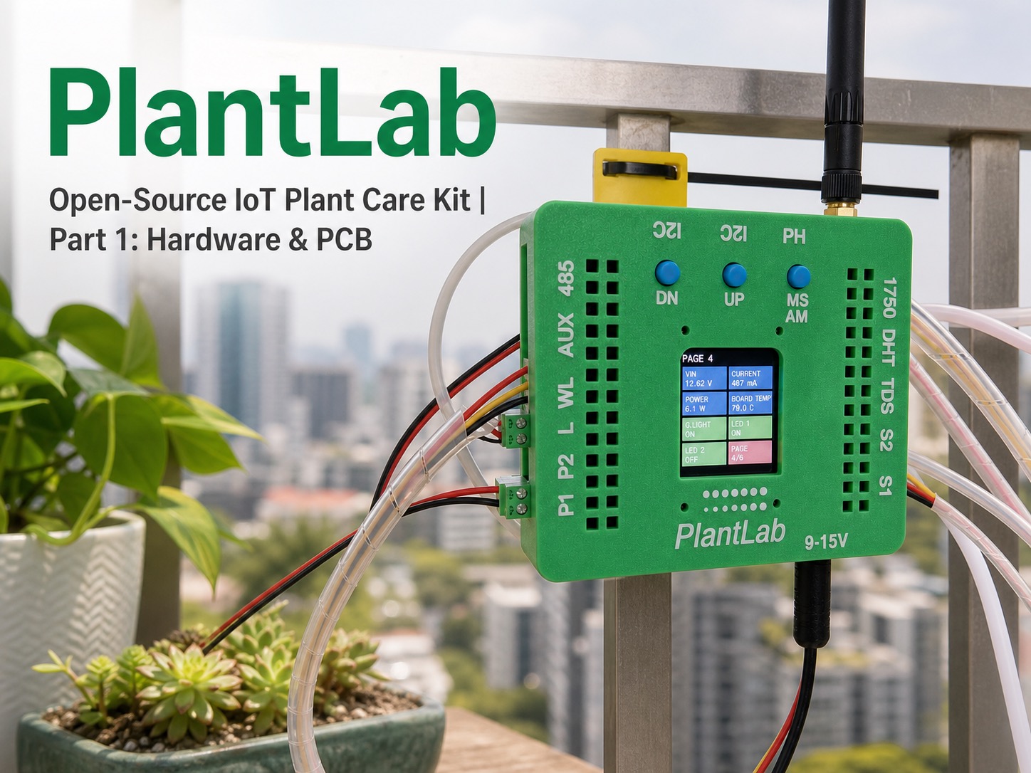
PlantLab is a beginner-friendly, open-source IoT plant care system built around a simple principle: use easily accessible, off-the-shelf modules—most of which you can buy on Amazon or AliExpress. No custom, hard-to-source parts, just affordable, ready-made modules and regular components.
The purpose of the PCB is to link these modules together with connectors and ports in a clean way. It is a simple two-layer PCB with straightforward routing and as few extra components as possible. There are still some surface-mount parts, but I chose easy-to-solder packages like 0805 to keep the hardware approachable for beginners.
The main board connects to modules through connectors. Sensors use XH2.54 ports, and actuators like pumps or grow lights use plug-and-play screw terminals, so you only wire up what you need—keep it simple.
So, what exactly does PlantLab do? It is a functional plant care assistant for your plants. It monitors key environmental factors—soil moisture, nutrient level, water level of the tank, air temperature, humidity, and light intensity—and reacts automatically: it waters the plant when the soil gets dry, turns the grow light on or off based on the light condition, and alerts you if the water level gets too low. Plus, it is built around the ESP32-S3, a popular microcontroller with built-in WiFi and Bluetooth, making it easy to add IoT features to the plant care system.
Best of all, everything you need to clone the project is free to download: schematics, PCB Gerber files, Arduino code, and enclosure files. No design work required—just order the parts, print, and build.
Project repository: https://github.com/RadHiveFun/plantLab
In this first part of the series, we’ll dive into the hardware side of PlantLab: the idea, the components and sensors we chose (and why), the schematic design, the PCB layout, and the basic enclosure design. By the end of this post, you’ll have a clear picture of the hardware platform, and in the next parts we can move further into assembly, testing, and code.
2. What This Project Can Do
PlantLab keeps your plants healthy with simple, automated features—all built with easy-to-source modules and beginner-friendly hardware. Here’s exactly what it does:
- Automatic Watering: Triggers water pumps when soil moisture drops below your set threshold, taking the guesswork out of watering.
- Water Level Monitoring: Uses an M03 or D2LS-A water level sensor to check the water tank level, so you’ll know when to refill (with a buzzer alert option).
- Grow Light Control: Controls an external grow light based on light intensity readings from the BH1750 sensor or daily schedules.
- Environmental Monitoring: Tracks air temperature, humidity (DHT22), and light intensity (BH1750), with real-time data displayed on the TFT screen.
- Manual Control: Three physical buttons on the board allow manual control of actuators like water pumps, grow light, etc.
- Flexible Connectivity: Sensor modules connect through XH2.54 connectors, while actuators like pumps and grow lights connect through plug-and-play screw terminals.
- More Sensors: An RS485 port is reserved for some agriculture-grade sensors. Additional I2C ports are also left for more sensor modules.
All these features work together to create a low-budget, smart plant care system—perfect for beginners who want to learn IoT and electronics while keeping their plants alive.
3. All Actuators & Sensors Used
Every component used in PlantLab is chosen for its affordability, ease of use, and availability on online markets like Amazon or AliExpress. Below is a breakdown of sensor modules and actuators, with a focus on what they do and how they contribute to the system.
3.1 Main Controller
ESP32-S3 Development Board: The brain of PlantLab. It is a high-performance ESP32-S3 development board with plenty of GPIO pins for connecting and controlling external devices. It supports Arduino C++ and MicroPython code—perfect for makers. The ESP32-S3 also has built-in WiFi and Bluetooth, so you can add IoT functions later if you want.
3.2 Sensor Modules (Core & Optional)
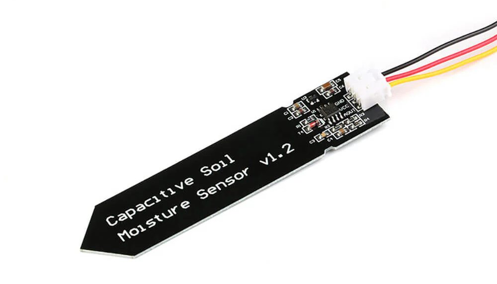
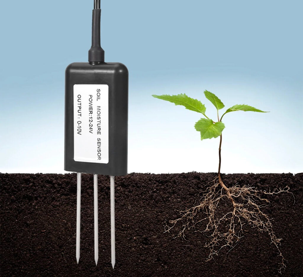
- Soil Moisture Sensors (2x): These are the core of the automatic watering system. Inserted into different parts of the soil (for example, near the plant’s stem and near the edge of the pot), they measure soil moisture independently. The system can then average the two readings to get a more reliable soil moisture value for the whole pot. This helps avoid false readings caused by uneven soil moisture, which is common in potted plants, and reduces the chance of overwatering or underwatering. They are simple capacitive sensors—easy to wire, affordable, and connected to the ADS1115 ADC module (along with the TDS sensor) to improve measurement accuracy. The ESP32-S3’s built-in ADC is good enough for many small projects, but here we also want to show another simple option for more stable analog readings.
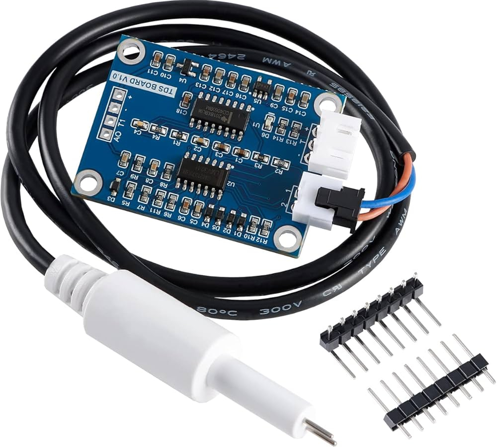
- TDS Sensor (Total Dissolved Solids sensor, Optional): Ideal for hydroponic setups (growing plants without soil) or anyone who wants to monitor water quality for potted plants. It measures the total dissolved solids (TDS) in water, which is related to nutrient concentration—higher TDS means more dissolved minerals, while lower TDS may indicate nutrient deficiency. Together with the two soil moisture sensors, it is connected to the ADS1115 ADC module to improve measurement precision. The ADS1115 connects via I2C, requires minimal wiring, and works well with the ESP32-S3, making it a simple add-on when a more precise and stable ADC reading is needed.
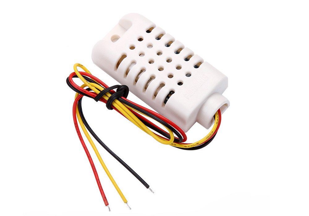
- DHT Temperature & Humidity Sensor: Monitors the air temperature and humidity around your plants. This data helps you understand how the environment affects plant growth—for example, if humidity is too low, you might need to mist your plants.
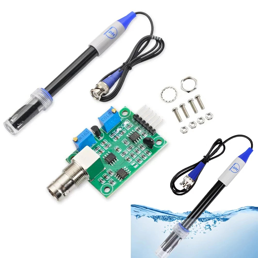
- pH Sensor: Measures the acidity or alkalinity of the water. This is useful for hydroponic setups or nutrient-water monitoring, because pH affects how well plants can absorb nutrients.
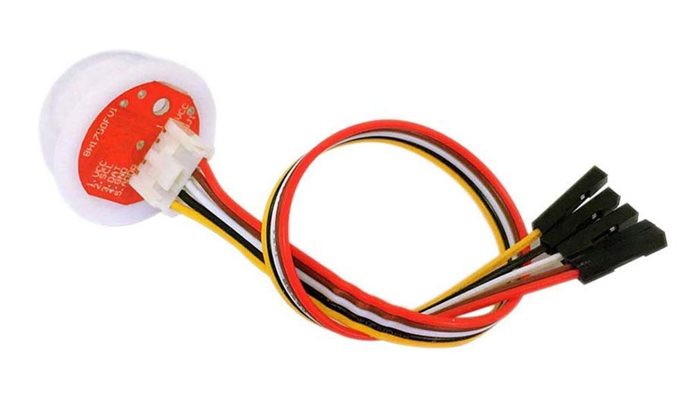
- BH1750 Light Intensity Sensor: A regular environmental sensor that measures the light intensity around your plant. This tells the system when to turn the grow light on or off, or adjust its brightness, so the plant can get enough light even on cloudy days.
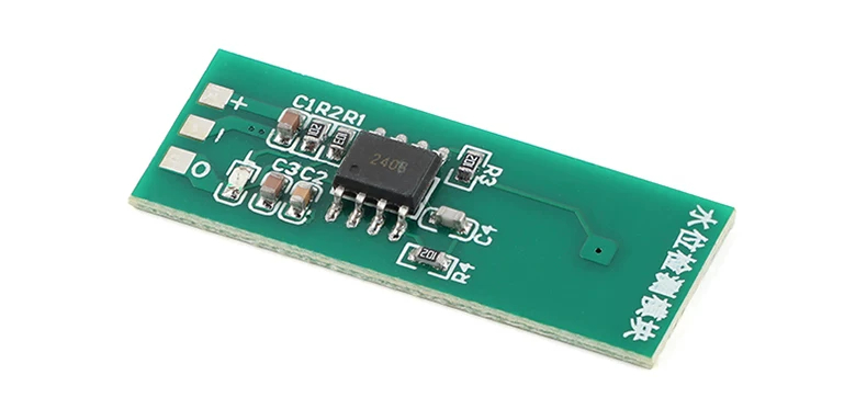
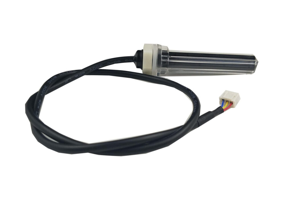
- M03 or D2LS-A Water Level Sensor: For water level monitoring, we give up the ultrasonic sensor and use these two simpler water level sensors instead. The M03 module is a small non-contact water level sensor, which can be fixed outside the water tank to detect whether the water reaches a certain position. The D2LS-A is another useful choice, especially for hydroponic setups. It can be put into the water tank or nutrient reservoir directly, so the system can know whether the water level is still safe for the pump and plant roots. Compared with the ultrasonic solution, these sensors are easier to place in a small tank, take less space, and are good enough for the low-water warning function of PlantLab.
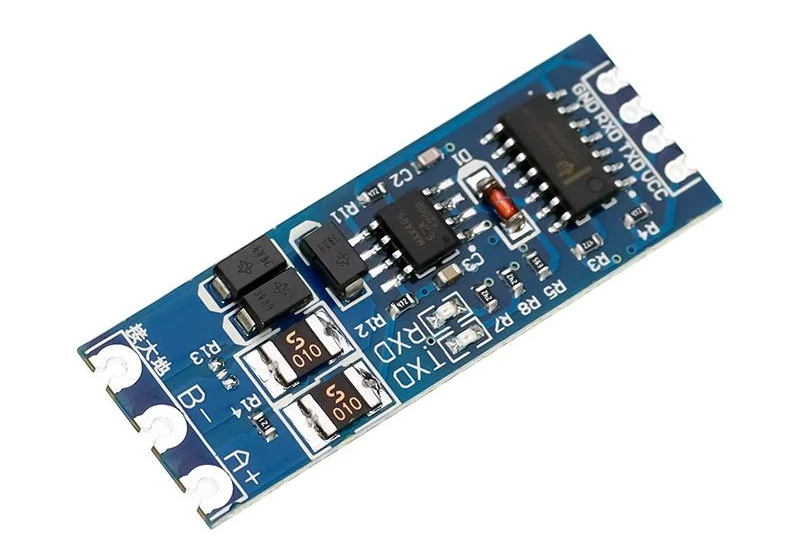
- RS-485 Agricultural Sensor (Optional): A specialized sensor for advanced plant care. It measures soil fertility, including nitrogen (N), phosphorus (P), and potassium (K)—the three key nutrients plants need to grow. It connects via RS-485, which is a common communication protocol used in some professional agricultural sensors.
3.3 Actuators (Core & Optional)
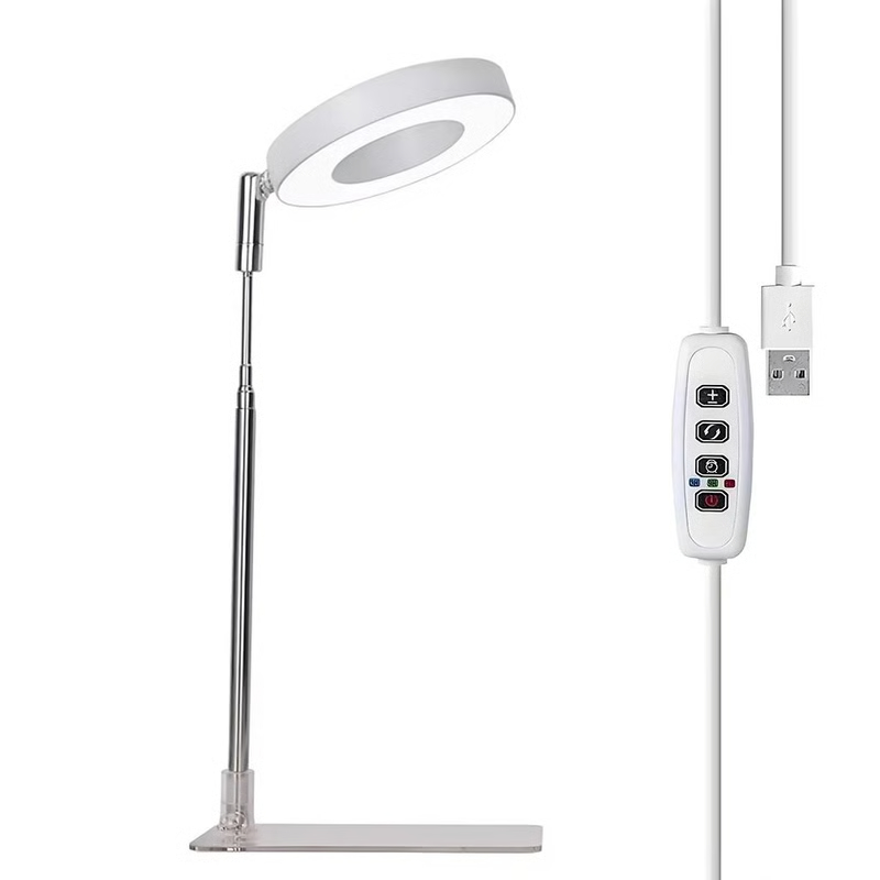
- 5V Low-power Grow Light (Optional): Provides supplemental light for your plants, especially if they are in a low-light area. The system can turn the light on/off or control the brightness based on timing settings or ambient light levels.
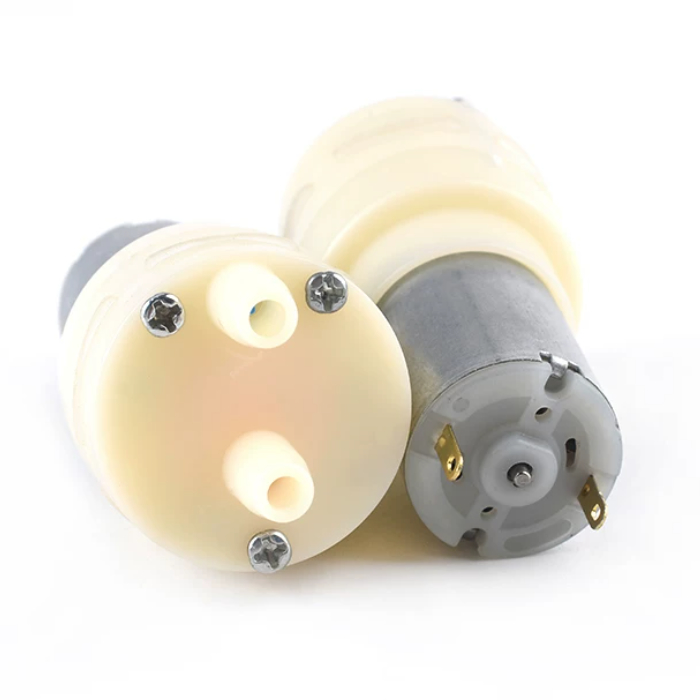
- 5V Submersible Water Pump (Watering, Optional): The core actuator for automatic watering. When the soil moisture sensors detect dry soil, this pump turns on to water your plants—small, quiet, and perfect for desktop or small plant setups.
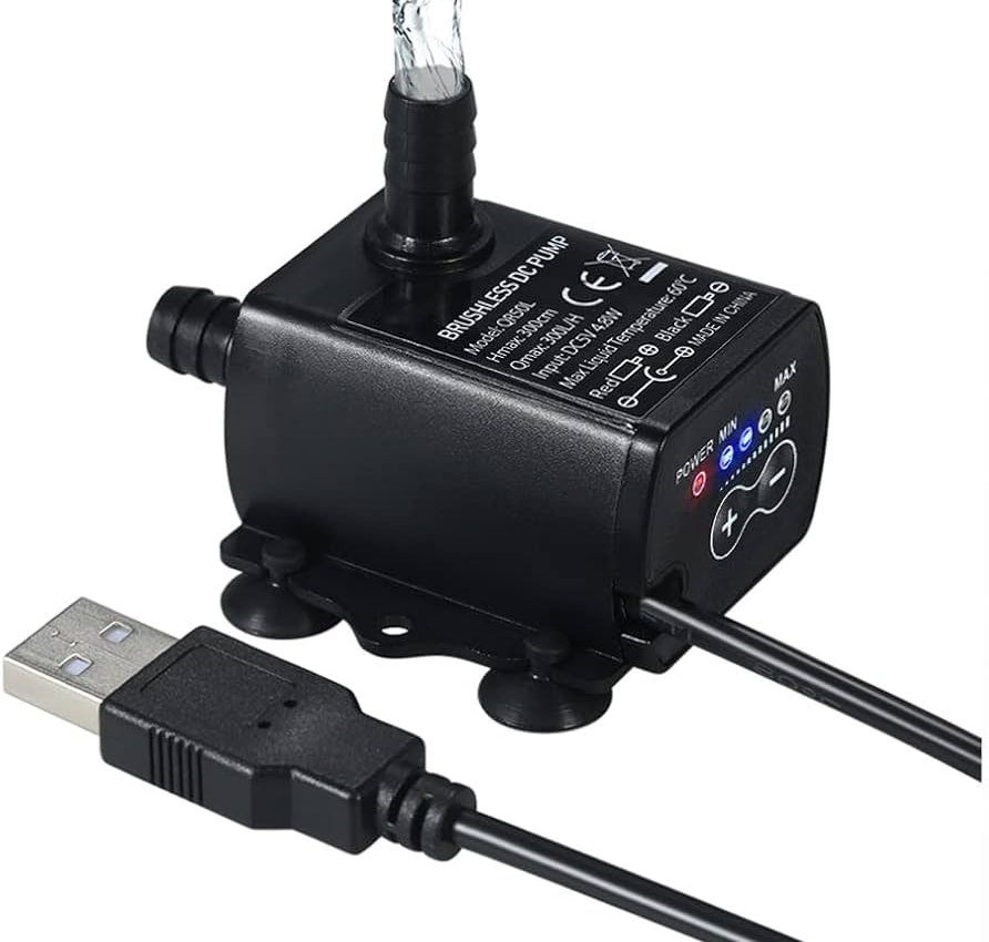
- 5V Water Pump (Water Tank Refill or Watering, Optional): Used to automatically refill the water tank. It can be triggered when the water level sensor detects a low water level, or when manual control is activated.
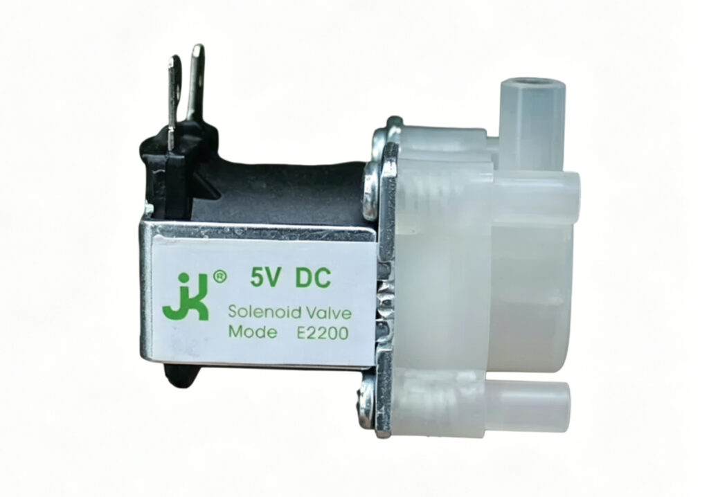
- 5V Solenoid Valve (Optional): Reserved for drainage of the water tank. It uses the same low-side MOSFET driving method as the pumps and other 5V actuators.
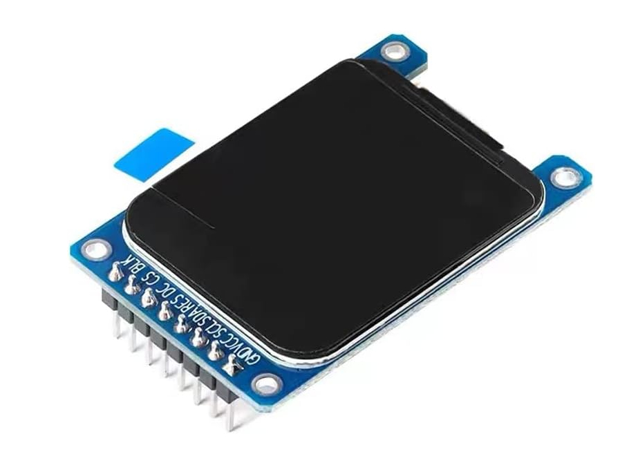
- 1.69″ TFT Display: Shows real-time data at a glance—soil moisture, temperature, humidity, light intensity, and water tank level. It can also display the system status, such as “Watering in progress”.
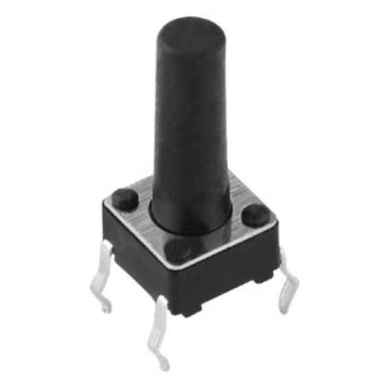
- Three Physical Buttons: For manual control and settings adjustment. Use them to navigate the TFT menu, set moisture/light thresholds, trigger watering manually, or turn the grow light on/off—great for overriding the automatic system when needed.
3.4 Expandability
We have two I2C ports reserved on the PCB, making it easy to add more sensors or modules later. Whether you want to add a second temperature/humidity sensor, a CO2 sensor, or any other I2C-compatible sensor, you can plug it in without reworking the PCB—perfect for makers who want to experiment and expand the project over time. These ports are clearly labeled on the PCB for easy identification.
4. System Architecture
4.1 Power Management Path
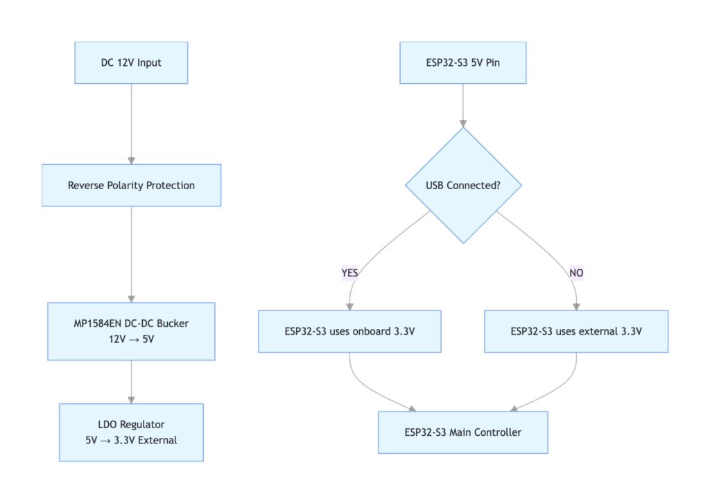
The board accepts 12V DC input, which first goes through a reverse-polarity protection circuit. The MP1584EN DC-DC module steps it down to 5V, and an LDO regulator further converts it to 3.3V to form an external power rail for the connected sensor modules. The pH sensor module is powered by 5V. Actuators such as pumps, the grow light, and the DC fan are also powered by the 5V line.
Since we use a ready-made ESP32-S3 dev board, we have to decide where the dev board gets its 3.3V power from: its own USB power path or the external 3.3V rail from the LDO. To handle this, the circuit detects USB connection through the dev board’s 5V output pin. If USB is connected (5V detected), the ESP32-S3 uses its onboard 3.3V power. If USB is not connected, it switches to the external 3.3V rail, ensuring normal operation in both scenarios.
4.2 Peripheral Connection Path
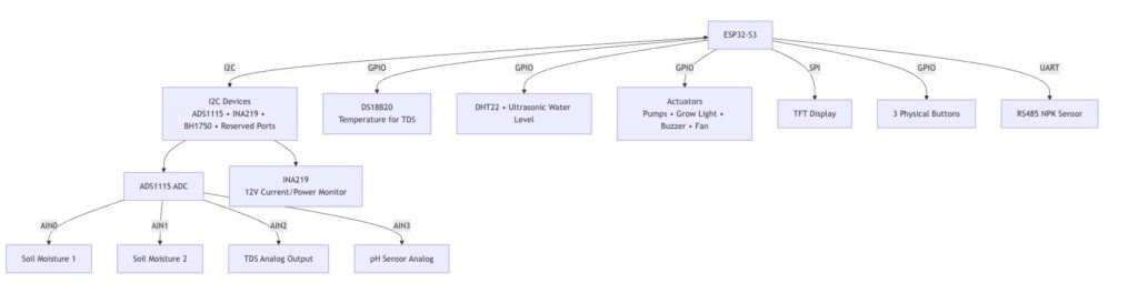
As the system core, the ESP32-S3 connects all peripherals through I2C, GPIO, SPI, and UART interfaces to handle data collection and device control.
The I2C bus connects the ADS1115 ADC module, INA219 power monitor, BH1750 light sensor, and spare I2C ports. The ADS1115 uses all four analog channels: AIN0/AIN1 for soil moisture, AIN2 for the TDS sensor, and AIN3 for the pH sensor. The INA219 monitors the 12V input by measuring voltage, current, and power. The BH1750 collects light intensity, and the spare I2C ports support future expansion.
GPIO pins interface with the DS18B20 (TDS temperature compensation), DHT22 (temperature/humidity), and water level sensor to collect related data. The RS485 interface connects to an NPK sensor to collect soil nutrient data. Meanwhile, the ESP32-S3 controls actuators (water pumps, grow light, buzzer, cooling fan) via GPIO to realize automatic watering, light control, and warning alerts.
The system also connects a TFT display through SPI for showing live measurements, and three physical buttons for manual control or settings.
5. Schematic & PCB Design
5.1 Schematic
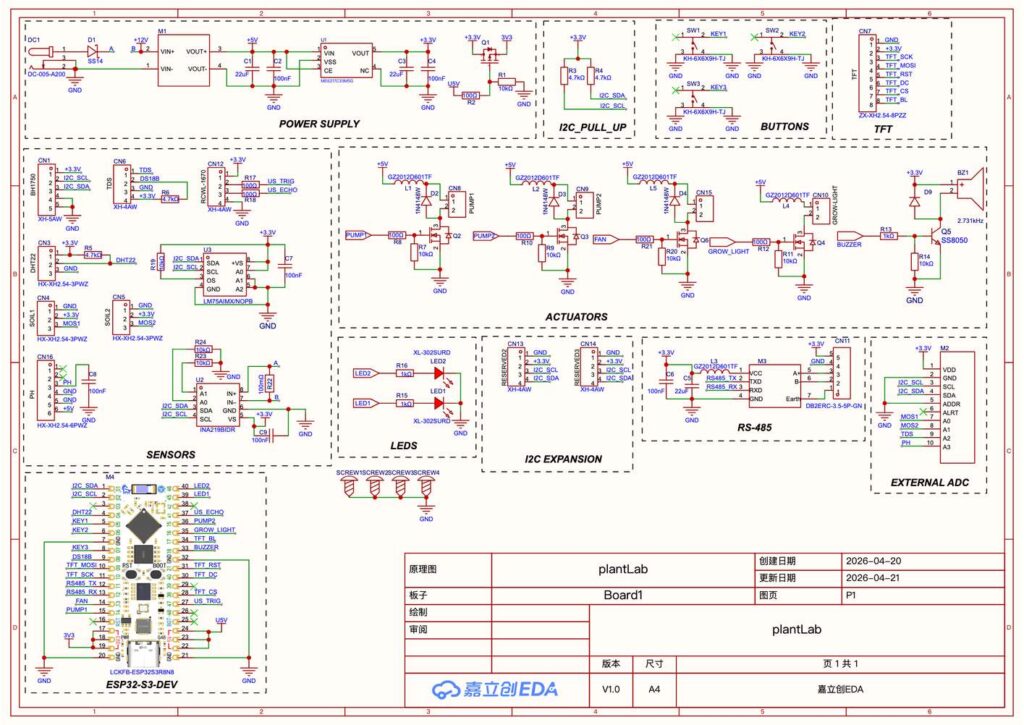
This PlantLab smart plant growth and care controller is designed around the ESP32-S3 development board (M4), with dedicated GPIO pin assignments for sensor modules and actuator modules, plus a dedicated onboard 3.3V power switching circuit.
5.1.1 Actuator Drive & GPIO Allocation
All external actuators (5V only) are switched by AO3402 N-channel MOSFETs (Q2, Q3, Q4, Q6) to provide stable load control and better heat handling. The dedicated GPIO control mapping is defined as follows:
GPIO 14: Water pump 1 control (via Q2), for actuators with current draw below 1A@5V
GPIO 15: Water pump 2 control (via Q3), for actuators with current draw below 1A@5V
GPIO 16: Grow light on/off and dimming control (via Q4)
GPIO 13: Cooling fan control (via Q6), for actuators with current draw below 1A@5V
An S8050 NPN transistor (Q5) is used on GPIO 18 to drive the onboard buzzer, providing simple warning and status feedback.
5.1.2 ADS1115 ADC & Sensor Interface Design
The ADS1115 (M2) 16-bit 4-channel external ADC is mounted on the global I2C bus and handles the analog-to-digital conversion for the analog sensors. All four analog input channels are fully allocated:
AIN0: Soil moisture sensor 1
AIN1: Soil moisture sensor 2
AIN2: TDS water quality sensor
AIN3: pH sensor analog output
A DS18B20 digital temperature sensor is directly connected to ESP32-S3 GPIO8 for real-time temperature compensation of TDS readings. Additional sensing devices include the I2C-based BH1750 ambient light sensor, DHT22 ambient temperature and humidity sensor, and water level sensor (GPIO41, GPIO47).
5.1.3 Communication, Buttons, and TFT Display
A UART-to-RS485 module (M3) using GPIO11 and GPIO12 is reserved for external professional agricultural soil NPK nutrient sensors.
The shared I2C bus also supports expansion of additional sensing modules.
Three independent physical buttons are configured for manual system operation, while an SPI TFT display interface shows the live measurements locally.
5.1.4 Powering the ESP32-S3 Dev Board
Automatic dual-power switching is realized via the SI2305 P-channel MOSFET (Q1). When USB is not connected to the ESP32-S3 dev board, the system is powered by the onboard 3.3V rail generated from the MP1584EN buck converter and ME6217C33M5G LDO. Once USB is plugged in, the circuit automatically cuts off the external 3.3V power path and switches to the ESP32-S3’s onboard USB power supply.
5.2 PCB Design
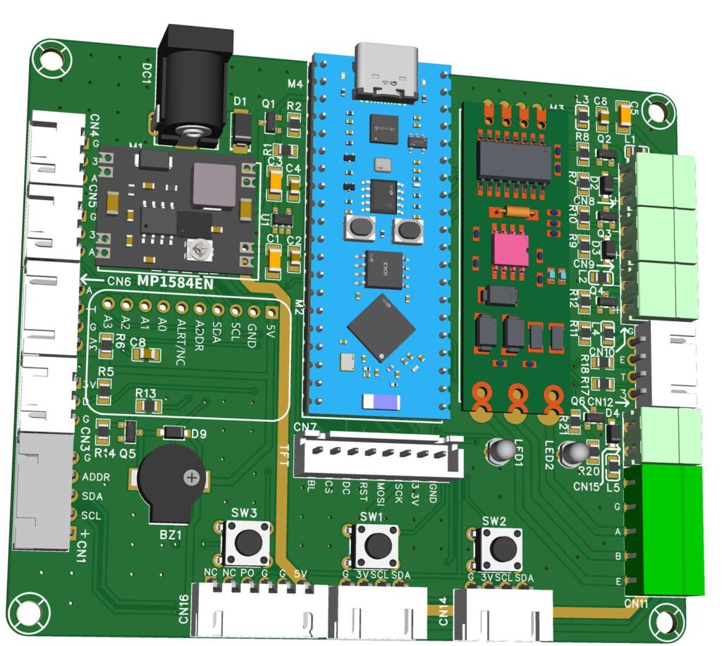
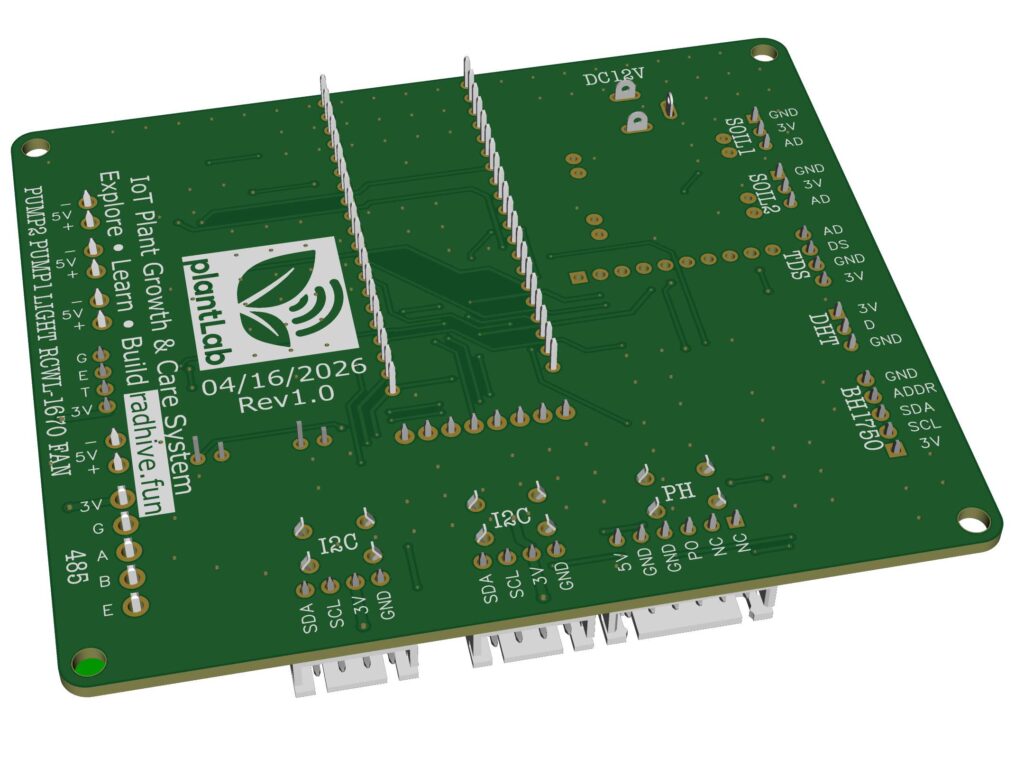
This is a two-layer PCB with practical, purpose-focused layout and intuitive interface arrangement.
All external connections to sensor modules, except the RS485 port, use standard XH2.54 header interfaces, while all actuator outputs use pluggable screw terminal blocks for fast wiring and convenient maintenance.
The INA219 power monitoring IC (U2) is placed directly underneath the MP1584EN power module to sample the current and power of the main 12V input path. The onboard LM75A temperature sensor (U3) sits below the ESP32-S3 module for local board temperature monitoring.
Interfaces are grouped by function. The function labels and signal names are clearly printed on the rear side of the PCB, making port identification and wiring straightforward, without having to check the schematic again and again.
The resistors and capacitors use 0805 or 1206 packages, the transistors and MOSFETs use SOT-23 packages, and ICs like the LM75A and INA219 use SOIC-8 packages. The 1N4148W diodes use SOD-123 packages. These are all regular parts, so you can get them easily from online markets.
6. 3D-Printed Case Overview
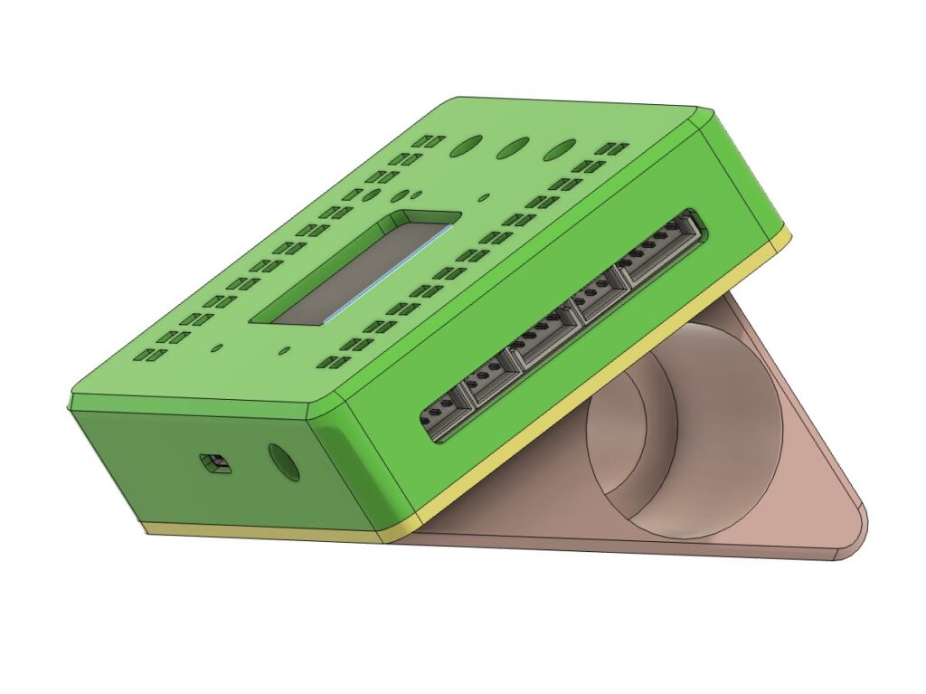
Besides the PCB, PlantLab also comes with a simple 3D-printed case. The purpose of this case is not to make the controller look fancy, but to make the hardware easier to use in a real plant-care setup. Since this project has many external modules connected to the main board, the enclosure has to keep the sensor ports, actuator terminals, display, buttons, and power input exposed and easy to reach.
The case is built around the shape of the PCB. The main board sits inside the enclosure, while the TFT display and three physical buttons face forward. With this layout, the controller can show live data directly on the front panel, and the buttons can still be used for menu control or manual operation. The display area is placed in the center, and the button positions are kept close to the lower side of the front panel, matching the layout of the PCB underneath.
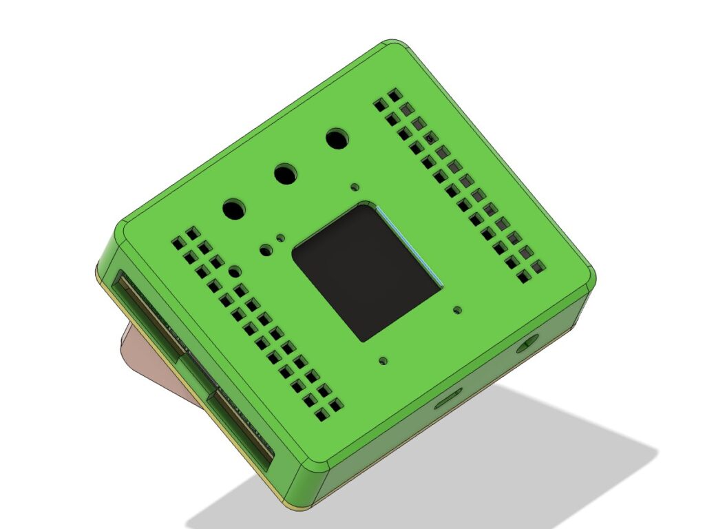
The side structure is mainly designed for the connectors. The XH2.54 sensor ports, screw terminals, power input, and expansion interfaces are arranged along the edges of the PCB, so the case leaves openings around these areas. This makes the enclosure more like a protective frame for the controller instead of a fully closed box. For a beginner project, this is useful because you can still clearly see where each cable goes, and the printed labels on the PCB can still help you identify each port.
The case uses a two-piece structure: a main shell for holding the PCB and a rear cover for closing the body. The overall shape is compact, but the front panel is made large enough for the display, button holes, ventilation openings, and the PlantLab logo area. The rear cover is kept flat and simple, so the whole controller can sit cleanly near a plant pot or on a small stand.
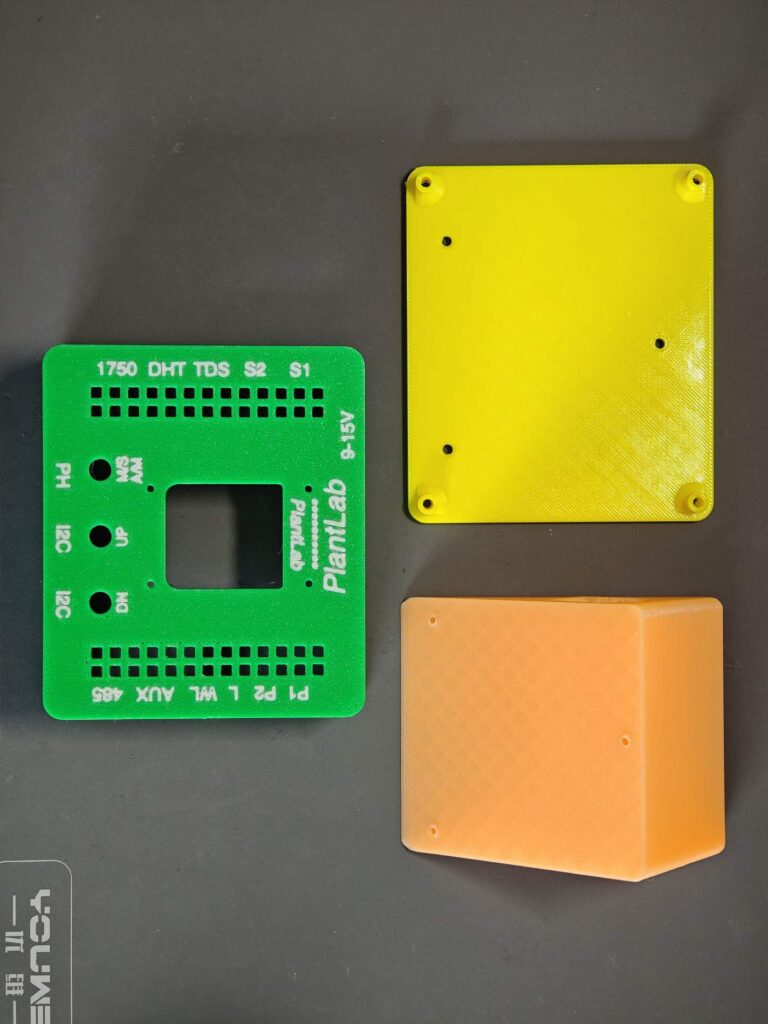
I also designed a small water-pump holder as part of the printed enclosure set. The pump holder sits at the back of the enclosure, and it also works as a stand for the housing.
Just like the PCB, the case is also open-source. You can use the original model if you want to build the same PlantLab controller, or you can modify the enclosure according to your own plant setup. This is why a 3D-printed case is a good match for this kind of open-source hardware project: it keeps the electronics fixed, but leaves the physical installation flexible.
7. Hardware Design Summary
So that is the basic hardware design of PlantLab. The whole system is built around the ESP32-S3 development board, with off-the-shelf sensor modules, simple 5V actuators, and a two-layer PCB used to connect everything together in a clean and beginner-friendly way.
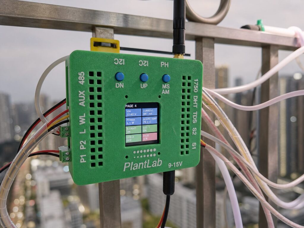
The main idea is to avoid making the hardware harder than it needs to be. For sensors, the PCB uses XH2.54 connectors, so modules like soil moisture sensors, DHT22, BH1750, M03/D2LS-A water level sensors, TDS sensor, and pH sensor can be connected directly. For actuators, the board uses screw terminals, which are more practical for pumps, grow light, fan, and other wired loads. This makes the wiring more reliable and much easier to understand.
The ESP32-S3 handles the main control logic, while the ADS1115 gives the system better analog input capability for soil moisture, TDS, and pH readings. The INA219 adds power monitoring on the 12V input side, and the reserved RS485 port leaves room for specific sensors like NPK modules.
Power design is also kept simple. The board takes 12V input, steps it down to 5V, then generates 3.3V for the low-voltage modules. The ESP32-S3 development board can work from USB during development, or from the external 3.3V rail when the system runs independently.
Together with the 3D-printed case, PlantLab becomes more than just a collection of modules on jumper wires. It becomes a small hardware platform for plant monitoring and automatic control, while still keeping the design open enough for makers to modify.
8. What Comes Next
In this first part, we mainly looked at the hardware design: what the project does, which sensors and actuators are used, how the ESP32-S3 connects to everything, how the schematic is arranged, how the PCB is designed, and what the 3D-printed case looks like.
In the next part, we will move from design to the real build. We will order the PCB, prepare the components, solder the board, install the modules, connect the sensors and actuators, and do the first power-on test. After that, we can upload the firmware and start checking the real sensor data from the plant setup.
Project repository: https://github.com/RadHiveFun/plantLab