
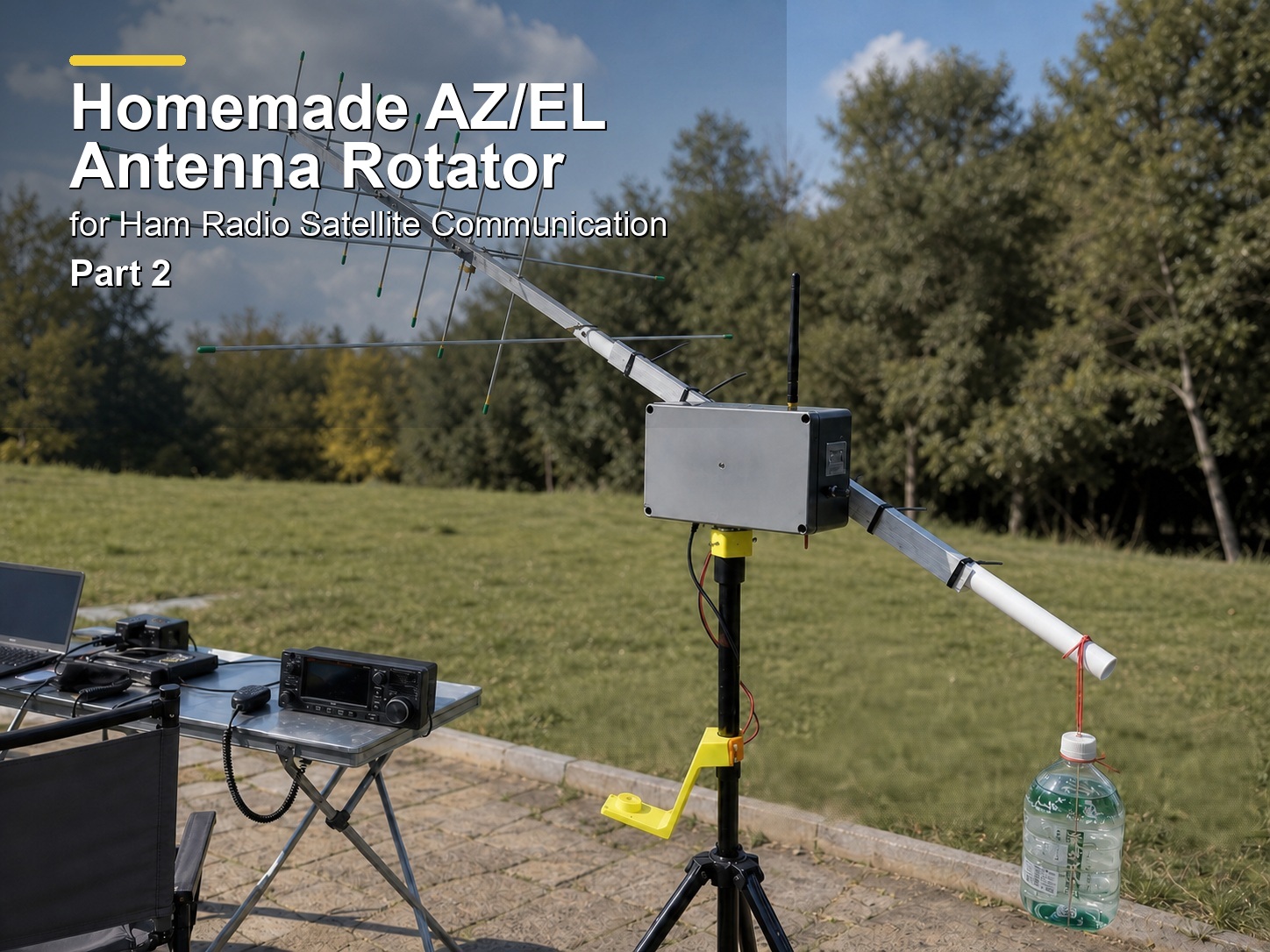
This is the second part of my article “A Homemade AZ/EL Antenna Rotator for Ham Radio Satellite Communication“. In the previous part, I introduced the project from its hardware perspective and mechanical structure. Today, we will center on its software concept, setup for use, and its known problems.
Software Flows#
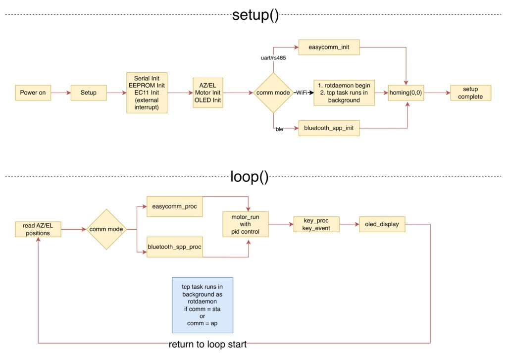
Upon power-on, the setup() function initializes the system in a one-time sequence: it first configures core hardware including the serial port, EC11 rotary encoder, EEPROM (to load saved communication mode and elevation offset), AZ/EL motors (two instances from motor class with built-in PID control), and OLED display. Next, it initializes the selected communication interface: for UART/RS485, it initializes the EasyComm-II protocol; for WiFi (STA/AP), it starts an AP or connects to a local network, then enables NTP time sync, launches the rotctld-compatible (hamlib rotctld daemon) TCP server as a background FreeRTOS task; and for Bluetooth, it initializes the classic SPP service. Finally, the system executes a homing sequence to move the rotator to the reference position (AZ=0°, EL=0°), completing initialization and entering the main loop.
The loop() function runs continuously to handle real-time operation: it first reads the current AZ and EL positions from the AS5600 encoders, then processes incoming commands based on the active communication mode (uart, rs485, sta, ap or ble), executing easycomm_proc for UART/RS485, bluetooth_spp_proc for Bluetooth, while WiFi commands are handled by the pre-launched background TCP task in setup(). After command processing, it runs the motor control logic (rotator_run) to drive the rotator to target positions, scans and processes manual key/encoder inputs, and updates the OLED display with real-time status, before repeating the entire cycle to maintain continuous, responsive operation.
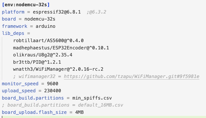
This is the general view of the software flow. There are many variables and structs used for storing the status of the rotator, running the motors with PID control, and parsing the commands. I would say, the code works, but it may still have some bugs, as I am not an expert programmer. The code was written in PlatformIO under the Arduino framework. See the picture below for the library dependencies.
Set it Up and Use#
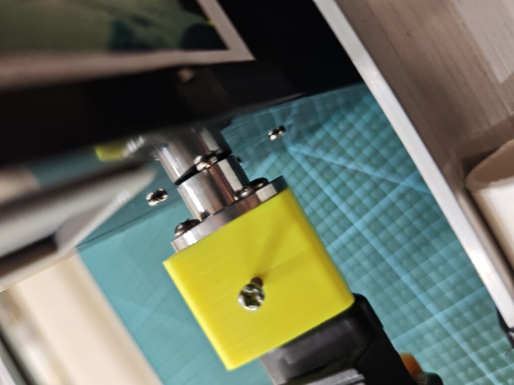
Before putting it into use, we need to install the rotator onto a tripod. In my case, I mounted the rotator onto a lightweight tripod used for photography lights, with the use of a 3D printed adapter. The flanged shaft coupler was first mounted onto the adapter by 4 screws, then the adapter with the coupler was installed onto the light stand.
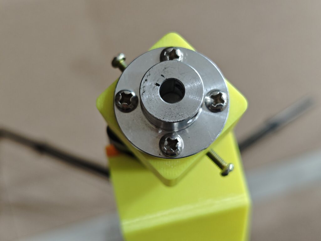
The rotator (shaft of AZ motor) was then put onto the flanged shaft coupler mounted on the tripod, by securing the two grub screws in the coupler. When mounting the shaft of AZ motor into the coupler, a small gap about 1-2mm was reserved in order to ensure smooth and frictionless rotation between the rotator’s enclosure and the top surface of the coupler.
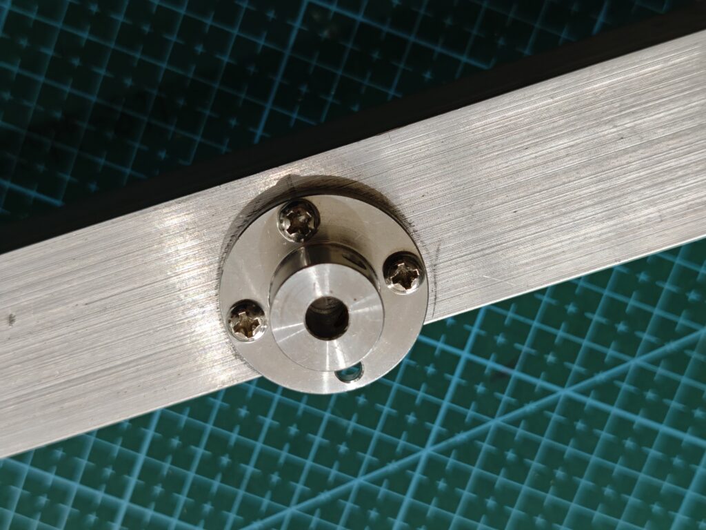
Another flanged shaft coupler for the EL motor was secured onto the aluminum angle bar. As the angle bar I used was not wide enough for covering the whole round surface of the coupler, only 3 screws were used for securing the flange onto the bar. I threaded the drilled holes, so no hex nuts were used on the other side of the angle bar. The flanged shaft coupler was put at the mid position of the bar.
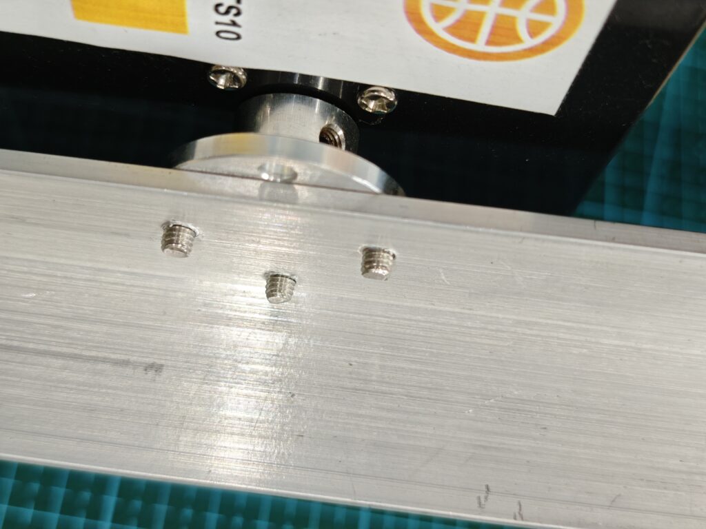
When mounting the angle bar to the EL motor, a gap about 1-2mm was also reserved there to ensure smooth elevation. In my setup, a short PVC was used to extend the length of the angle bar, so that the longer arm of force will reduce the total counter-balancing weight. The antenna could be mounted on the other side of the bar by tightening the cable ties. In the picture, a 3D printed bracket was also installed for mounting the IC-705.
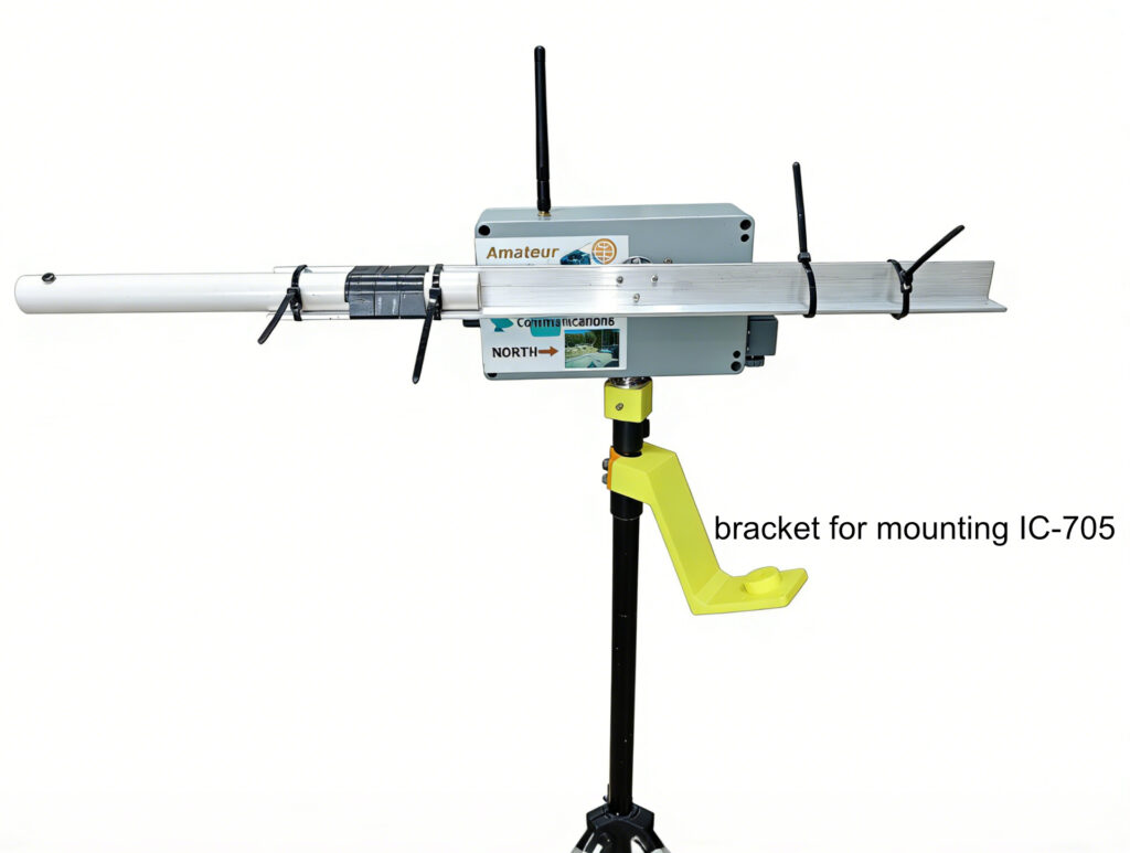
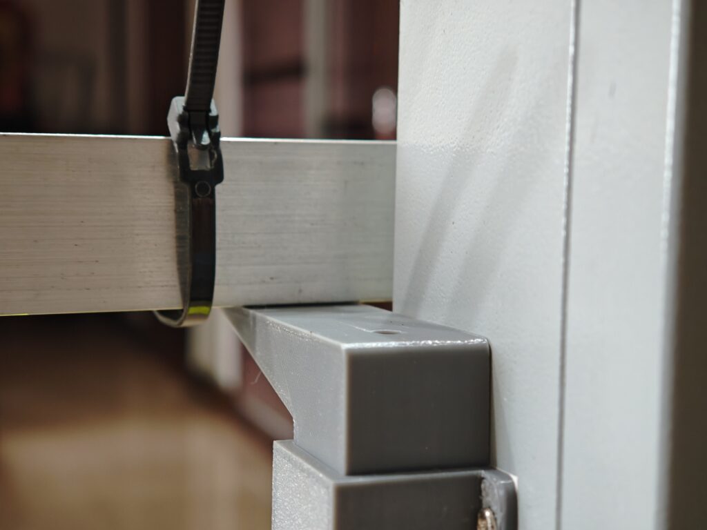
When securing the angle bar to the EL motor, the grub screws should be screwed tightly onto the motor’s D-shaped shaft and the angle bar should be as close as possible to the 3D printed antenna support. There may still be some space between them, so we could configure the “offset” value in the menu to ensure the angle bar touches the antenna support a bit, or nearly touches it, when the EL angle is 0. This aims to protect the EL motor’s gear from damage when the antenna is initially mounted on the front end without any counter-balancing force from the other side of the bar.
A bottle containing 1.5 liters of water was used as the counter-balancing force from behind. There was a thin lead tied at the end of the PVC pipe. This was so important, as without the counter-balancing force, the EL motor was unable to elevate the yagi antenna, and the motor’s shaft might move incorrectly or stop somewhere with the internal gears being damaged.
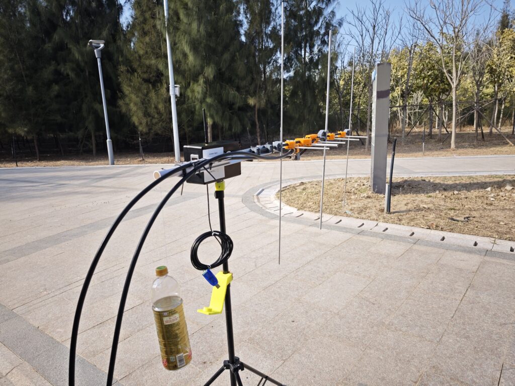
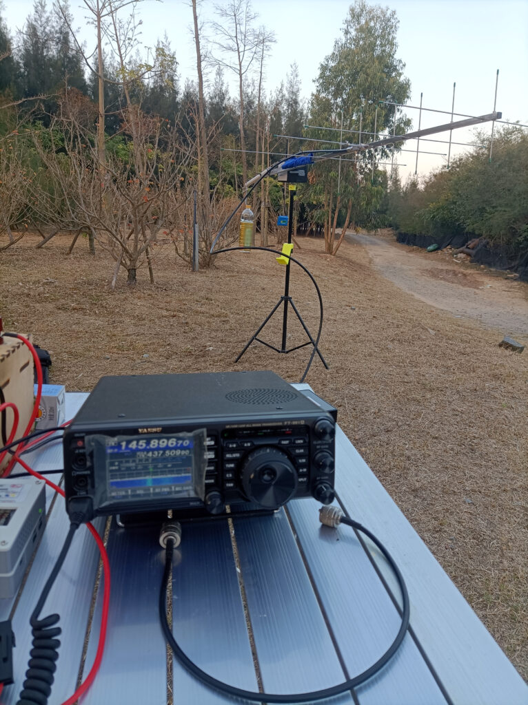
In my test, the rotator draws less than 300mA with both AZ and EL motors running when working at 12V. When powered by 18650 (3S) batteries, it would last for a whole week, as we don’t let it work continuously, because you can’t work the amateur satellites for a whole day, and you normally have to stop and wait until the next pass. The picture below shows the setup in my first QSO to ISS, at a time when the rotator was still under test (plastic enclosure with built-in shield made from copper tapes).
The Control Software#
Generally, the rotator works with any software that is compatible with EasyComm-II (wired link), hamlib rotctld daemon (WiFi), and the Look4Sat protocol (Bluetooth SPP). As of today, I have successfully used the rotator to work with Gpredict (PC through WiFi), Dtrac (phone app, WiFi), and Look4Sat (phone app, Bluetooth).
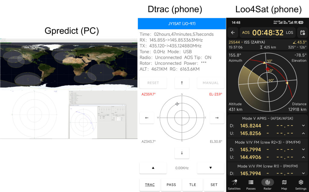
As a portable satellite ground station, I would prefer controlling the rotator from my phone apps. All of the software listed above is capable of automatically controlling the antenna’s pointing while controlling your radio’s VFO to the right frequency for both receiving and transmitting. Look4Sat has a big update in v4 for controlling your radio, but I have never tested it, as I am not used to it. For FM satellite, it is fine to have your radio controlled by the software, as there are no other frequencies (it only has one channel) to go for an effective contact. But for the linear satellites, many stations could work at the same time because it has a wider range of frequencies (RS-44 60KHz) to go, and I don’t know how the software could know my desired transmitting frequency (uplink) so it could calculate the receiving frequency (downlink) based on the doppler shift principle, or vice versa.
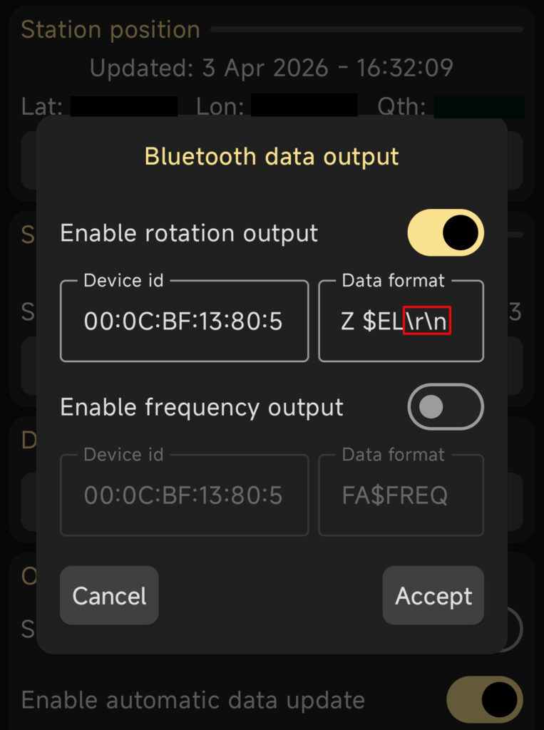
A special note for Look4Sat, we have to add \r\n (no space ahead of \) at the end of its default data string in order to let it work with the rotator perfectly.
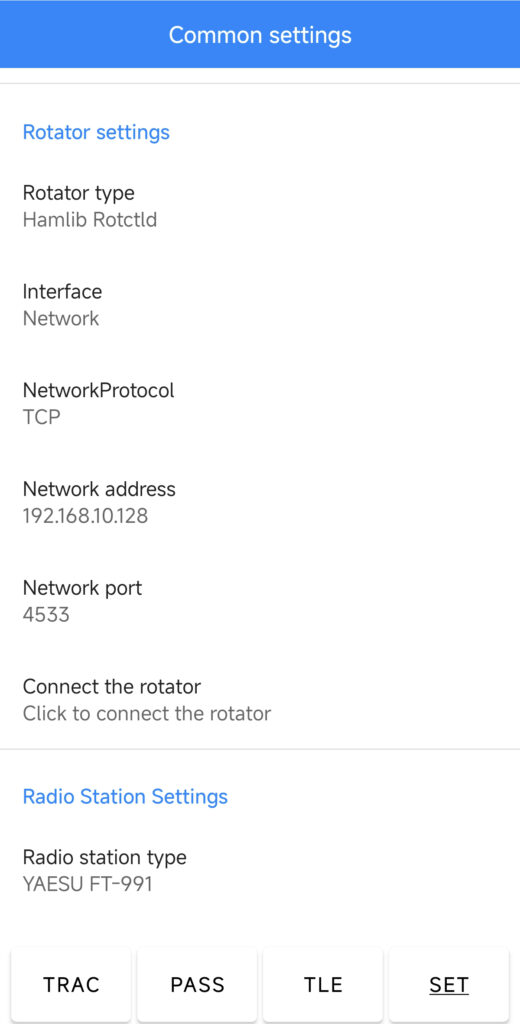
Settings for Dtrac are just as follows. The network address and port are the IP address of the rotator and its TCP port. I usually use the phone to start a WiFi hotspot, so the rotator can connect to my phone in WiFi STA mode.
| Software | Way of connection |
|---|---|
| Gpredict | Hamlib Rotctld Daemon through WiFi connection |
| Dtrac | Hamlib Rotctld Daemon through WiFi connection |
| Look4Sat | its own protocol via Bluetooth connection |
Constraints#
Below are the major constraints of the rotator I’ve built:
- Supports only one antenna; it should be a U/V dualband antenna.
As restricted by its structure, this kind of antenna rotator can only load up one antenna, and a cross Yagi is preferable or perhaps the best one. As a result, it is suitable for the lower orbit FM satellites, which have no special requirements on the antenna systems. For the linear birds, the far more complicated, typically dual Yagi antennas with 6-7 elements are the basic setup, perhaps with preamps for the downlink. This obviously is not the stuff that a portable ground station could handle. However, this doesn’t mean that you can’t work the linear birds with this setup; it works conditionally. I have worked the RS-44 with a U7V4 cross Yagi mounted on this rotator. It had a good working condition at higher elevation angles, but I lost the contact when the bird went down to the lower angles (<30 degrees).
- Needs counterweight to balance the rotation arm.
The counterweight is added to protect the motor’s gears, and it also keeps the balance between the front and back so as to prevent the working rotator on the tripod from falling over, making the tripod stable on the ground. In my case, for portable operation, I use a bottle of water as the counterweight, as it costs nothing.
- It gets some RF interference from the transmitting antenna placed close to the rotator.
This limitation results from its structure, as the EL motor directly tilts the antenna. So you have to fix the antenna on the arm (angle bar), where a flanged coupler connects to the motor’s shaft. The antenna is so close to the rotator that it causes some RFI problems. In my first version, the strong RFI caused the motor to run without control when transmitting (5W or more on UHF band). Finally, I added the copper tape shielding on the inner wall of the plastic housing in my second building, and it worked perfectly with the transmitting power of less than 20W. Similar results were also achieved in the newest aluminum housing.